 |
|||
|
|
|||
|
|
|||
| ||||||||||
|
|
 MWO 55-8115-202-40-1
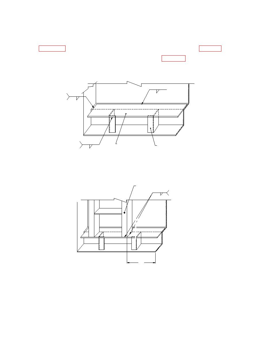
(31) Pull generator out on slides and locate plate, ladder, Item 3.10, (120K1917) overtop of stubs
left when ladder was removed. This bar should span the pieces left from the ladder when cut in
Place the ladder onto the bar, 6" from the upright corner post, and line up with the edge of bar so
that no part of the ladder protrudes beyond the container frame (Figure 25B).
1/4 1" - 4"
2X
1/4
FRONT CORNER
UPRIGHT POST
OMITTED
FOR CLARITY
ITEM 3.10
2X
EXISTING LADDER FRAME
1/4
LEFTOVER AFTER CUT IN
PARAGRAPH 4.4
Figure 25A
LADDER
2X
1/4
FRONT CORNER
FRONT CORNER
UPRIGHT POST
UPRIGHT POST
OMITTED FOR
OMITTED
CLARITY
FOR CLARITY
6.00
Figure 25B
(32) Re-weld ladder onto container with 1/4 inch welds at intersection of ladder and container
36
|
|
Privacy Statement - Press Release - Copyright Information. - Contact Us |
