 |
|||
|
|
|||
|
Page Title:
AC HEATER/EVAPORATOR BLOWER DOES NOT OPERATE IN ALL SPEEDS (LOW, MEDIUM, AND HIGH) - continued |
|
||
| ||||||||||
|
|
 DRAFT
TB 9-2320-364-13&P-1
AC HEATER/EVAPORATOR BLOWER DOES NOT OPERATE IN ALL SPEEDS
(LOW, MEDIUM, AND HIGH) - Continued
WARNING
Remove rings, bracelets, wristwatches, neck chains, and any other jewelry before working around
vehicle. Jewelry can catch on equipment and cause serious injury. Jewelry or tools may short
across electrical circuits or terminals and cause damage to equipment or severe burns or
electrical shock to personnel.
- - - - - - - - - - - - - - - - - - - - - - - - - - - - - - - - - - - - -
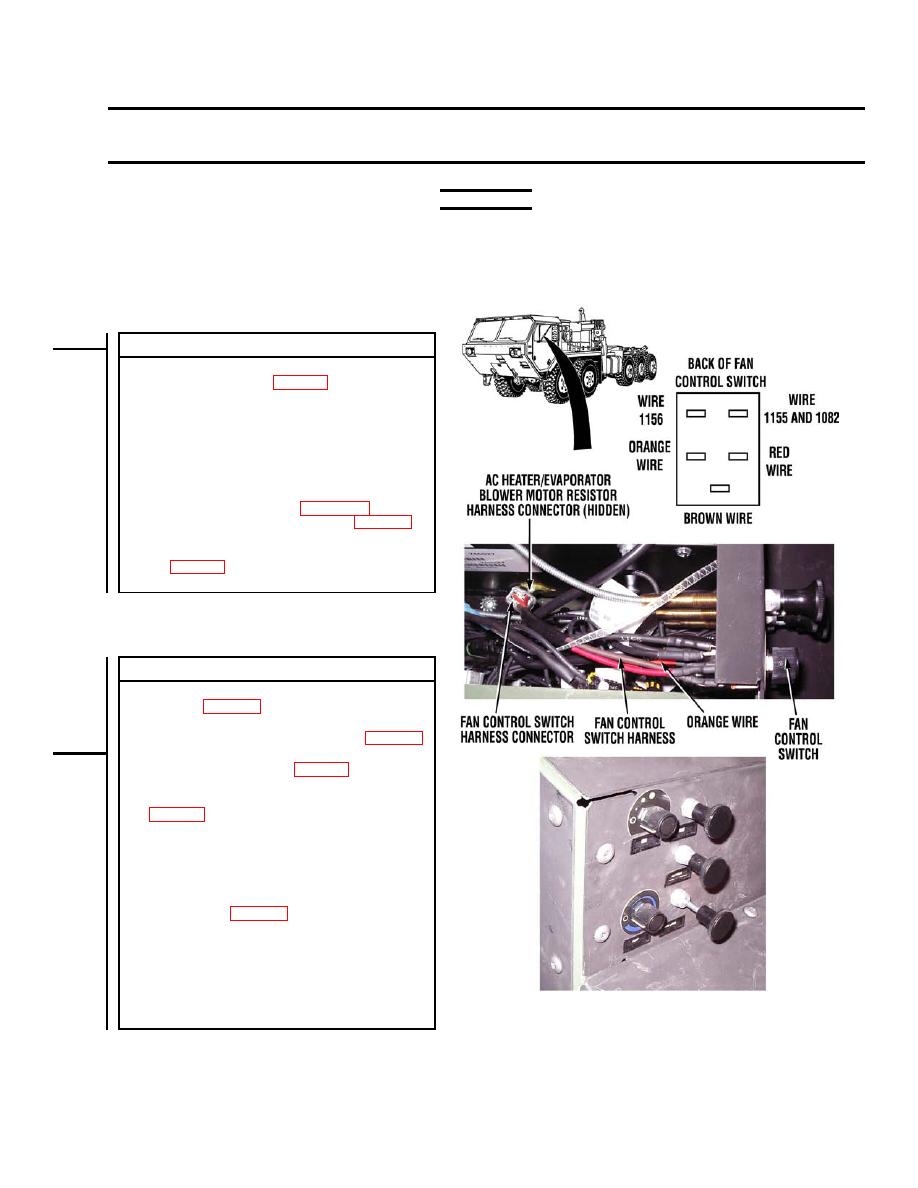
CONTINUITY TEST
(1) Disconnect fan control switch harness orange wire
from fan control switch (WP 0031).
(2) Set multimeter switch to ohms.
(3) Place positive (+) probe of multimeter on fan control
switch harness orange wire at AC heater/evaporator
blower motor resistor harness connector, terminal 3.
(4) Place negative (-) probe of multimeter on fan control
switch harness orange wire at fan control switch.
(a) If there is no continuity, repair fan control switch
harness orange wire (see Appendix A) or
replace fan control switch harness (WP 0031).
Verify repair, go to Step 15 of this fault.
(b) If there is continuity, replace fan control switch
fault.
VERIFY REPAIR
(1) If disconnected, connect fan control switch harness
connector (WP 0031).
(2) If disconnected, connect AC heater/evaporator
blower motor resistor harness connector (WP 0036).
(3) If disconnected, connect red, brown, and orange
wires on fan control switch (WP 0031).
(4) Install cover and four screws, washers, and
lockwashers on AC heater/evaporator assembly
(5) Install two upper plenums (TM 9-2320-364-20).
(6) Install heater compartment access panel and eight
screws (TM 9-2320-364-20).
(7) Turn engine start switch ON (TM 9-2320-364-10).
(8) Turn fan control switch to low, medium, and high
speed positions (WP 0004). Verify AC heater/
evaporator blower operation in all positions.
(a) If AC heater/evaporator blower does not operate
in all positions, fault is not corrected. Turn fan
control switch and engine start switch to OFF
and notify Supervisor.
PLSAC170
(b) If AC heater/evaporator blower operates at all
positions, fault has been corrected.
END OF WORK PACKAGE
|
|
Privacy Statement - Press Release - Copyright Information. - Contact Us |
