 |
|||
|
|
|||
|
Page Title:
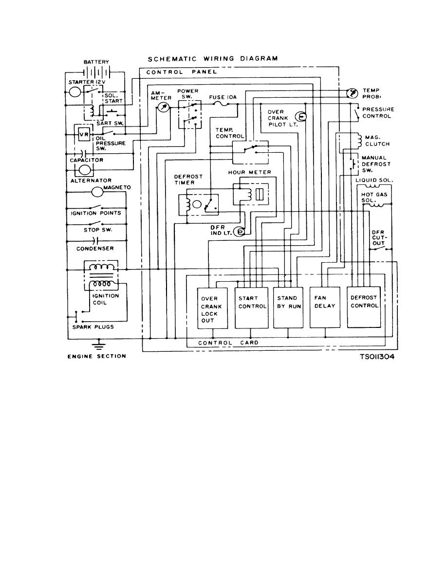
Figure 1-4. Wiring Diagram RMP-J/I-10G Gasoline Engine Driven |
|
||
| ||||||||||
|
|
 TM 5-4110-217-14
Figure 1-4. Wiring Diagram RMP-J/I-10G Gasoline Engine Driven
c.
Repair and Replacement Standards. Desired Clearance
Desired Clearance
Minimum
Maximum
(1) Engine (Model RMP-J/1-iOG)
Valve interference
1
Desired Clearance
angle ......................
Minimum
Maximum
Crankshaft main
Valve tappet to
bearing ...................
0.0025
0.0038
cylinder block ....
Crankshaft end play ....
0 006
0 012
clearance ..................... 0.0150
0 0030
Crankshaft bearing ......
0 0015
0 0030
Valve stem in ...............
Camshaft end play ......
0.0(03
guide - intake ............... 0 0010
0.0025
Rod bearing
Valve stem in ...............
(forged rod) ..........
0.0006
0.0023
guide - exhaust ............ 0.0025
0.0040
Connecting rod
Valve seat inter- ...........
end play (ductile
ference width ............... 1/32
3/64
iron) ......................
0.002
0.016
Valve face angle .......... 44
Timing gear
Valve seat angle ......... 45
backlash ..............
0.002
0.003
1-7
|
|
Privacy Statement - Press Release - Copyright Information. - Contact Us |
