 |
|||
|
|
|||
|
Page Title:
Section II. FLYWHEEL, GEAR COVER, GOVERNOR CUP, TIMING GEARS AND OIL PUMP |
|
||
| ||||||||||
|
|
 TM 5-4110-217-14
Section II. FLYWHEEL, GEAR COVER, GOVERNOR CUP,
TIMING GEARS AND OIL PUMP
b. Repair. A magneto flywheel which has lost its
5-8. General.
magnetism can be remagnetized. Test by holding the
If engine disassembly is necessary, remove engine from
spark plug wire away from a clean metal part of the
refrigeration unit and first remove all the complete
engine while cranking. The spark should jump a 3/16-
assemblies. Individual assemblies can be removed and
inch gap with ease. Replace magnet (figure 3-17) if
serviced later, if necessary. Refer to Section I for
necessary.
removal of the engine accessories. Most engine repairs
c. Installation. Press on flywheel. Make sure the
will require the removal of blower housing group (13, fig.
steel key (202), (fig. 3-11) is used to lock the flywheel to
the shaft (199).
NOTE
5-10. Gear Cover (Fig. 3-11).
When disassembling the engine, keep
a. General. After removing the flywheel (127),
all parts in their respective order, such
flywheel key (202), the gear cover (135) can be removed.
as valve assemblies, rod caps for
b. Removal. Remove five screws (135A), (135B),
respective rod and piston assemblies,
and lockwashers (135C) holding gear cover assembly.
etc. Analyze reasons for parts failures.
Gently tap the gear cover with a soft-faced hammer to
Use new gaskets for reassembly.
loosen it.
5-9. Flywheel.
c. Repair. Replace leaking oil seal gasket (148),
a. Removal. To remove the flywheel, turn the
or defective governor shaft and arm (138), governor
flywheel mounting screw outward about two turns and
shaft yoke (139), or roll pin (137).
use Onan puller 420-0100 (or equivalent) and pull
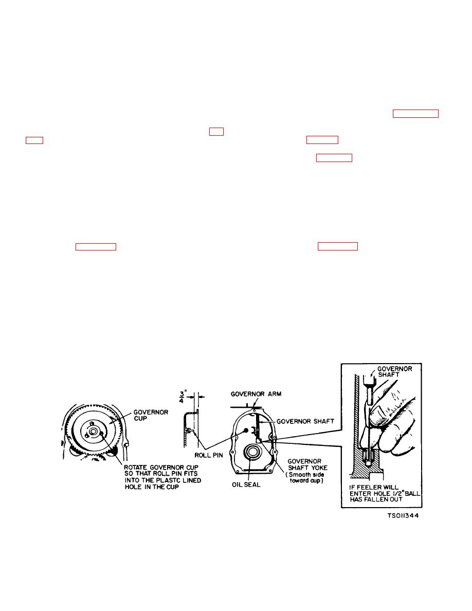
d. Installation (figure 5-11).
flywheel (127, figure 3-11).
CAUTION
CAUTION
When installing the gear cover, make
DO NOT use a screwdriver or similar
sure that the roll pin in the gear cover
tool or pry behind the flywheel against
engages the governor cup correctly.
the gearcase. The gearcase cover is
die-cast material and will break if undue
(1) Prior to installing the gear cover assembly
pressure is applied in this manner.
to the engine, adjust the stop pin to protrude to a point
Handle the flywheel with care. Do not
3/4-inch from the cover mounting surface.
drop the flywheel. A broken fin will
destroy the balance.
.
Figure 5-11. Gear Cover Assembly Installation (Model RMP- J/l-IOG
5-7
|
|
Privacy Statement - Press Release - Copyright Information. - Contact Us |
