 |
|||
|
|
|||
|
|
|||
| ||||||||||
|
|
 TM 5-4110-217-14
c. Installation.
Also, use a feeler to check 1/2-inch ball. Replace
missing ball. (Fig. 5-11.)
(1) When installing the governor cup, tilt the
(2) Turn the governor cup so that the plastic
engine so the gear is up. Put the flyballs in place and
lined hole is at the three o'clock position. The smooth
install the cup and snap ring on the center pin.
side of the governor yoke must ride against the governor
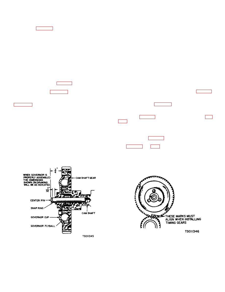
(2) The camshaft center pin extends out 3/4
cup.
inch from the end of the camshaft. This distance
(3) Turn the governor arm and shaft clockwise
provides an in out out travel distance of 7/32 inch for the
as far as possible and hold in this position until the gear
governor cup, as illustrated. Hold the cup against the
cover is installed flush against the crankcase.
flyballs when measuring. If the distance is less (the
engine may race, especially at no load), remove the
center pin and press a new pin in only the required
CAUTION
amount. Otherwise, grind off the hub of the cup as
Care must be taken not to damage the
required. The camshaft center pin cannot be pulled
gear cover oil seal
outward or removed without damage. If the center pin
extends out too far, the cup will not hold the flyballs
(4) Reinstall flywheel (para 5-9).
properly.
(3) Reinstall gear cover and flywheel (para 5-9,
5-11. Governor Cup (Fig. 5-12).
5-10).
a. Removal. Remove the gear cover assembly
5-12. Timing Gears (Fig. 5-13).
removing the snap ring from the cam shaft center pin.
a. General. If replacement of either the crankshaft
Catch the flyballs while sliding the cup off.
gear (153-1, fig. 3-11) or the camshaft gear (153-2, fig.
b. Repair.
(1) Replace any flyball that is grooved or has
one only. Use a gear pulling ring (420-0248) to remove
a flat spot. If the arms of the ball spacer are worn or
the crankshaft gear. Be sure to remove the lock ring
otherwise damaged, replace the entire timing gear set.
(155) first.
(2) The governor cup must spin freely on the
b. Removal (fig. 3-11).
camshaft center pin without excessive looseness or
(1) Remove flywheel, gear cover and governor
wobble. If the race surface of the cup is grooved or
cup (para. 5-9 thru 5-11).
rough, replace it with a new one.
(2) The camshaft gear (153-2) is pressed on
and keyed to the camshaft (181). The camshaft(181)
and gear (163-2) must be removed as an assembly after
first removing the crankshaft gear lock ring (155) and
washer (156). Before removing the camshaft
Figure 5-13. Timing Gear Removal and Installation
Figure 5-12. Governor Cup (Model RMP-J/1-10G)
(Mode RMP-J/I-1OG)
.
5-8
|
|
Privacy Statement - Press Release - Copyright Information. - Contact Us |
