 |
|||
|
|
|||
|
Page Title:
Figure 5-20. Cleaning Ring Grooves (Model RMP-J/1- IOG). |
|
||
| ||||||||||
|
|
 TM 5-4110-217-14
c. Cleaning, Inspections and Repair.
(1) Clean all parts in an approved cleaning
solvent. Dry thoroughly with clean lint-free clot Remove
carbon deposits from piston ring groove Use piston
groove cleaner tool to remove dirt grooves (fig. 5-20).
Blow out all oil passages with compressed air.
(2) Inspect piston for cracks, breaks, and
scored condition. Inspect clearances between piston pin
and piston. Piston pin is a thumb push fit. piston is
excessively loose on piston pin, install a new piston pin.
Inspect clearance between piston and cylinder wall.
Position piston In cylinder. Clearance between piston
and cylinder measured below o controlling ring, 90
degrees from pin, should 1 0.0025 to 0.0045-inch.
(3) Inspect the piston for fractures at the ring
lands, skirts and pin bosses. Check for wear at the ring
land using new rings and a feeler gauge shown in figure
Figure 5-21. Inspecting Ring Lands (Model RMP-J/1-
IOG)
(4) Check for excessive ring side clearance (
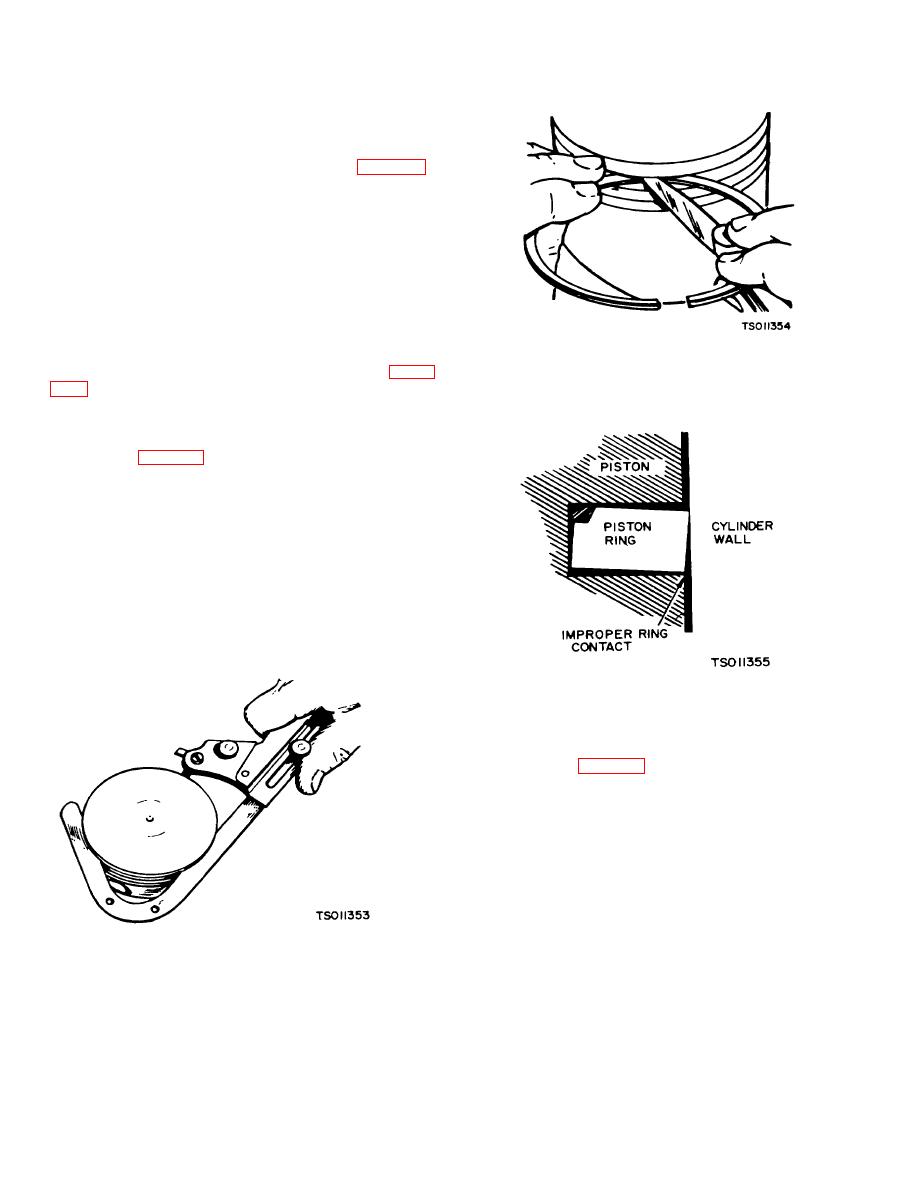
improper width rings. These can result in ring breakage.
New rings in worn ring grooves will n have good cylinder
wall contact (fig. 5-22).
(5) Check for pistons showing signs of be
scoring or burring, excessive skirt clearance, wax or
worn ring lands, fracture or damage from detonation.
Replace piston pins showing fracture scored bores, or
bores out of round more than 0.002-inch.
(6) Use a new piston pin to check the p
bushing in the connecting rod for wear. Clearance piston
pin In rod should be 0.0001 to 0.0006.
d. Reassembly.
(1) Before installing new rings on the piston
check the ring gap by placing each ring squarely in
Figure 5-22. New Ring Worn Piston Ring Groove (Model
RMP-J/1 -IOG)
its cylinder at a position corresponding to the bottom of
its travel (see fig. 5-23). The piston ring gap in cylinder
should be 0.010 min. to 0.023 max. Rings which are
slightly oversize may be filed as necessary to obtain the
correct gap, but do not use rings which require too much
filing. Standard size rings may be used on .005-inch
oversize pistons. Other oversize rings must be used with
corresponding oversize pistons. Rings of the tapered
type are usually marked top on one side, or identified in
some other manner and the ring must be installed with
this mark toward the closed end of the piston.
(2) Drive piston pin bushing(205) m connecting
Figure 5-20. Cleaning Ring Grooves (Model RMP-J/1-
rod (197).
IOG).
(3) Position piston (206) on connecting rod
(197). Thumb-push piston pin (204) through piston and
connecting rod. Secure pin with two retaining rings
(203).
Change 3 5-13
|
|
Privacy Statement - Press Release - Copyright Information. - Contact Us |
