 |
|||
|
|
|||
|
Page Title:
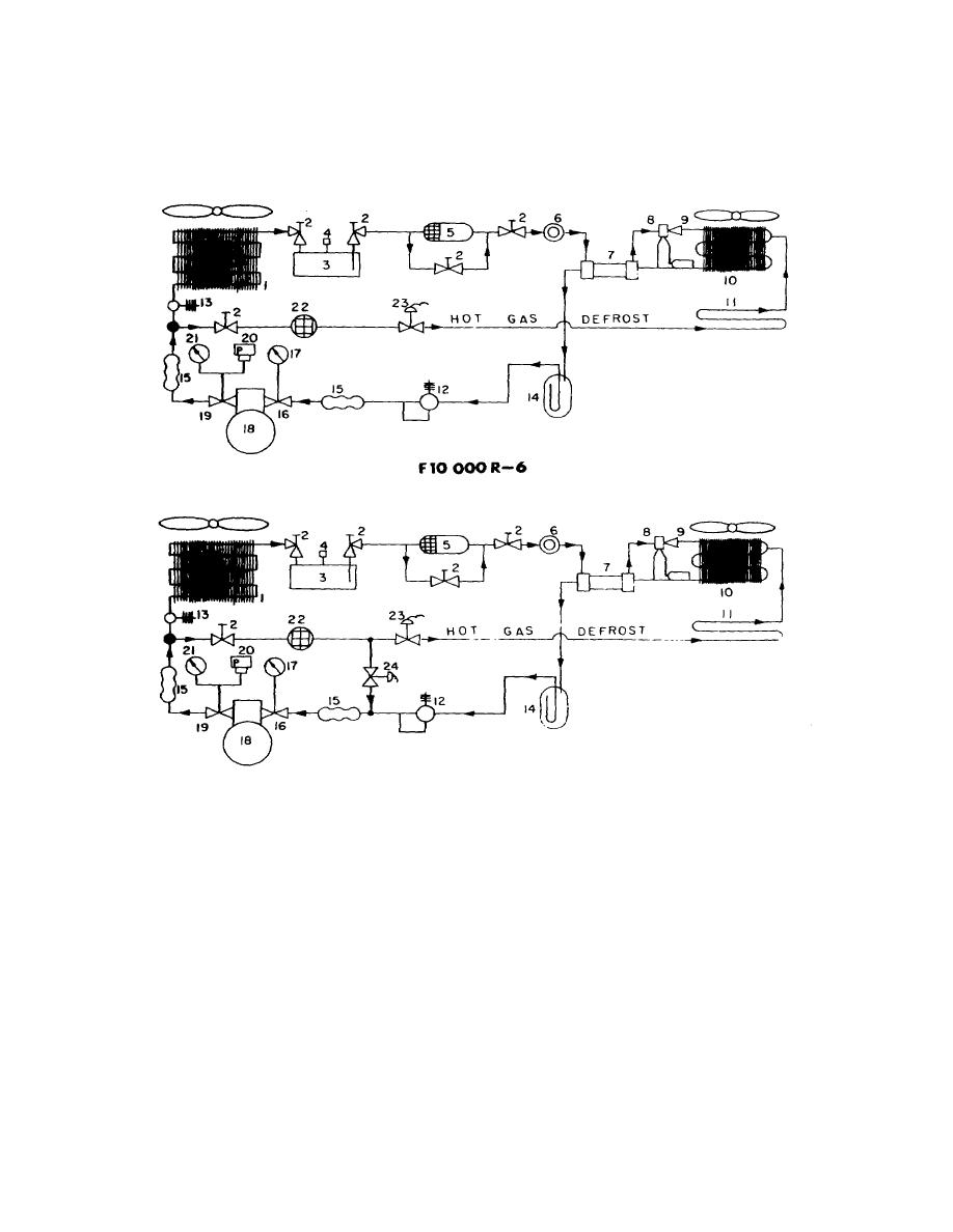
Figure 1-4. Refrigeration Flow Schematic |
|
||
| ||||||||||
|
|
 TM 5-4110-234-14
TO 40R7-5-7-1
c. The ice and frost on the evaporator coil and the drain pan melt.
d. When the defrost cycle is complete the unit automatically returns to the refrigeration cycle.
F10 OOORG-2
14.SUCTION ACCUMULATOR
2.SHUT OFFVALVE
15.VIBRATION ABSORBER
3.RECEIVER
16.SUCTION SERVICE VALVE
4.FUSIBLE PLUG
17.COMPOUND GAGE
5.FILTER DRIER
18.COMPRESSOR
6.MOISTURE LIQUID INDICATOR
19.DISCHARGE SERVICE VALVE
7.HEAT EXCHANGER
20.HEAD PRESS CUTOUT SWITCH
8.THERMOSTATIC EXPANSION VALVE
21.HEAD PRESSURE GAGE
9.DISTRIBUTOR
22.STRAINER
IOEVAPORATOR
23.HOT GAS SOLENOID
II.DRAIN PAN COIL
24.HOT GAS COMPRESSOR
12.CRANKCASE PRESSURE REGULATOR
BY PASS SOLENOID
13.DISCHARGE PRESSURE REGULATOR
(FIO,O00 RG-2 ONLY)
TS-4110-Z34-14/1-4
Figure 1-4. Refrigeration Flow Schematic
1-7 (1-8 blank)
|
|
Privacy Statement - Press Release - Copyright Information. - Contact Us |
