 |
|||
|
|
|||
|
Page Title:
OIL PRESSURE GAGE (Model F10000RG-2 Only) |
|
||
| ||||||||||
|
|
 TM5-4110-234-14
TO 40R7-5-7-1
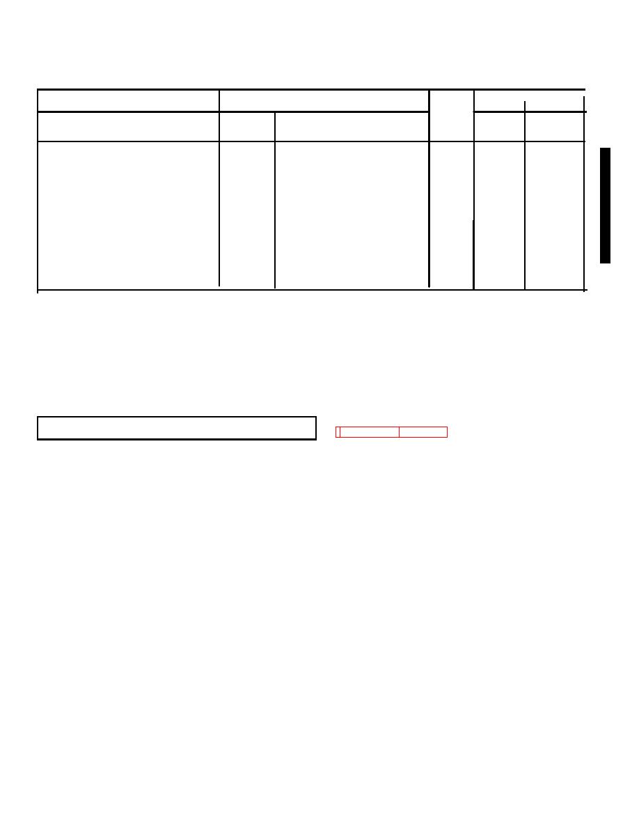
Table 4-5. WIRE LIST F10000RG-2 (cont.)
TERMINATION
TERMINATION
AWG
LENGTH
Wire
FROM
TERMINAL TYPE
TO
TERMINAL TYPE
Size
IN
CM
TB1-7
MS-25036-108
DS1-2
MS-25036-108
16
26
66.0
E1-GRD
MS-25036-108
TB1-E1
MS-25036-108
16
14
35.6
TB1-1
MS-25036-108
S9-1
MS-25036-108
16
18
45.7
TB1-El
MS-25036-108
K6-2
42460-1 (00779)
16
160
406.4
TB1-E1
MS-25036-108
El-GRD
MS-25036-108
16
13
33.0
S9-1
MS-25036-108
S-15-NO
42332-2 (00779)
16
15
38.1
Engine
MS-25036-157
Unit Frame
MS-25036-157
10
10
25.4
L2-1
MS-25036-108
S5-NO
42332-2 (00779)
16
160
406.4
L2-2
MS-25036-108
TB1-E1
MS-25036-108
16
160
406.4
K7-1
MS-25036-108
S1-NC
42332-2 (00779)
16
25
63.5
S16-C
42332-2 (00779)
Z1-1
42332-2 (00779)
16
120
304.8
TB1-7
MS25036-108
S14-C
42332-2 (00779)
16
15
38.1
(4)
Remove the meter.
c.
Replacement.
(1)
Position the meter on the panel and, while observing the meter lead tags, reconnect the meter.
(2)
Secure the meter in place using the three screws and nuts.
(3)
Reconnect power.
4-22.
OIL PRESSURE GAGE (Model F10000RG-2 Only)I See figures 4-14 and 4-15.
a. Removal.
(1)
Disconnect power.
(2)
Remove the two screws and lock washers and open the hinged control panel.
(3)
Disconnect the flare nut joint to the female coupling.
(4)
Remove the female coupling.
(5)
Remove the two nuts and lock washers and the clamp from the back of the gage.
(6)
Pull the gage from the panel.
b.
Installation.
(1)
Install the gage through the panel and clamp in place using the clamp, nuts and lock washers supplied
with the gage.
(2)
Connect the female coupling and the flare nut and tube assembly to the gage.
(3)
Close the hinged control panel and secure with two screws and lock washers.
(4)
Connect power.
Change 1 4-35
|
|
Privacy Statement - Press Release - Copyright Information. - Contact Us |
