 |
|||
|
|
|||
|
Page Title:
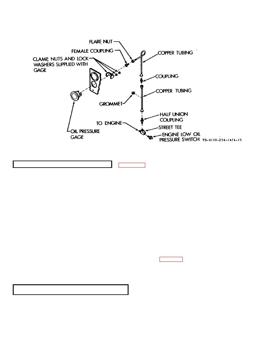
Figure 4-15. Oil Pressure Gage F10000RG-2 |
|
||
| ||||||||||
|
|
 TM5-4110-234-14
TO 40R7-5-7-1
Figure 4-15. Oil Pressure Gage F10000RG-2
4-23.
AMMETER (Model F1000RG-2 Only) See figure 4-14.
a. Removal.
(1)
Disconnect power.
(2)
Remove the two screws and lock washers and open the hinged control panel.
(3)
Tag and remove the wires.
(4)
Remove the nuts, lock washers, and clamp that secure the gage to the control panel.
(5)
Pull the gage from the front of the control panel.
b.
Installation.
(1)
Install the gage through the panel and clamp in place using the clamp, nuts and lock washers supplied
with the gage.
(2)
Connect the wire leads. See tags and wiring diagram figure 4-6.
(3)
Close the hinged control panel and secure with two screws and lock washers.
(4)
Connect power.
4-24.
FUEL LEVEL GAGE (ModelF10000RG-2Only) See figure4-14.
a. Removal.
(1)
Disconnect power.
(2)
Remove the two screws and lock washers and open the hinged control panel.
4-37
|
|
Privacy Statement - Press Release - Copyright Information. - Contact Us |
