 |
|||
|
|
|||
|
Page Title:
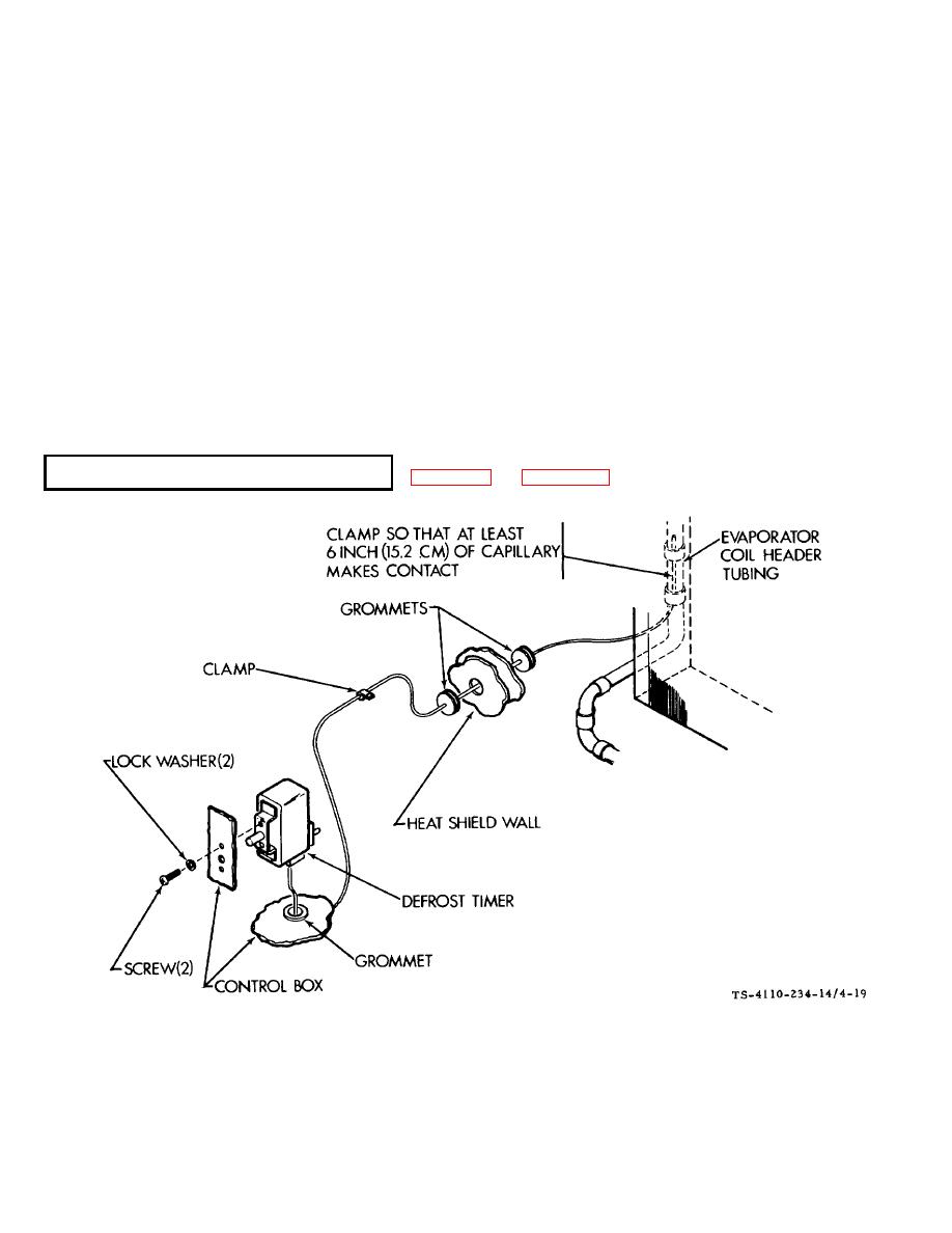
DEFROST TIMER (MODEL F10000R-6 ) |
|
||
| ||||||||||
|
|
 TM5-4110-234-14
TO 40R7-5-7-1
(6)
Remove the three attaching screws and nuts and pull the gage from the panel.
b.
Installation.
(1)
Mount the gage in the panel with the three screws and nuts.
(2)
Install the coupling on the valve and loosely connect the flare nut.
(3) Slightly crack (turn valve stem clockwise) the compressor suction valve to allow a very slight amount of
refrigerant to escape through the capillary line at the flare nut to clear the capillary of moisture and air.
(4)
Immediately tighten the flare nut.
(5) Again turn the suction valve stem fully counterclockwise and then turn it one turn clockwise to "backseat
and crack" the valve. Reinstall the protective cap over the valve stem.
(6)
Using a water and soap solution check the newly connected fittings for leaks.
(7)
Close the access doors and connect power.
4-31.
Figure 4-19. Defrost Timer F10000R-6
4-43
|
|
Privacy Statement - Press Release - Copyright Information. - Contact Us |
