 |
|||
|
|
|||
|
|
|||
| ||||||||||
|
|
 TM5-4110-234-14
TO 40R7-5-7-1
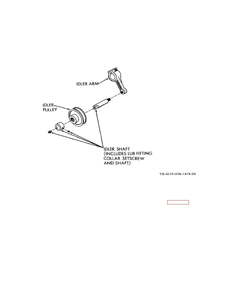
c. Installation/Assembly.
(1)
Screw the idler shaft into the idler arm and tighten using an open end wrench on the machined flats. Do not
use vise grips or a pipe wrench or any device that would mark the shaft bearing surface.
(2)
Slide the idler pulley on the shaft and place the collar on the end of the shaft, snug against the pulley. Be sure
the pulley spins freely.
Figure 4-24. Idler Pulley F10000RG-2
(3)
Tighten the collar setscrew.
(4)
Slide the assembled idler pulley, shaft and arm onto the idler support bar. See figure 4-23.
(5)
Position the idler pulley bar support and secure it in place with two each cap screws and lock nuts in the
upper holes and a cap screw and lock washer in the lower hole.
(6)
Be sure the belt is in place on the clutch pulley and the outer groove of the compressor pulley.
(7)
Position the idler pulley against the belt being careful that the three pulleys aline and that the belt is running
parallel with the face of the pulleys.
(8)
Push the idler pulley to bring proper tension in the belt. Proper tension is a deflection of 1/2 inch (1.3 cm)
midway between the pulleys. Tighten the idler pulley setscrew.
(9)
Close the access doors.
(10)
Connect power.
4-58
|
|
Privacy Statement - Press Release - Copyright Information. - Contact Us |
