 |
|||
|
|
|||
|
Page Title:
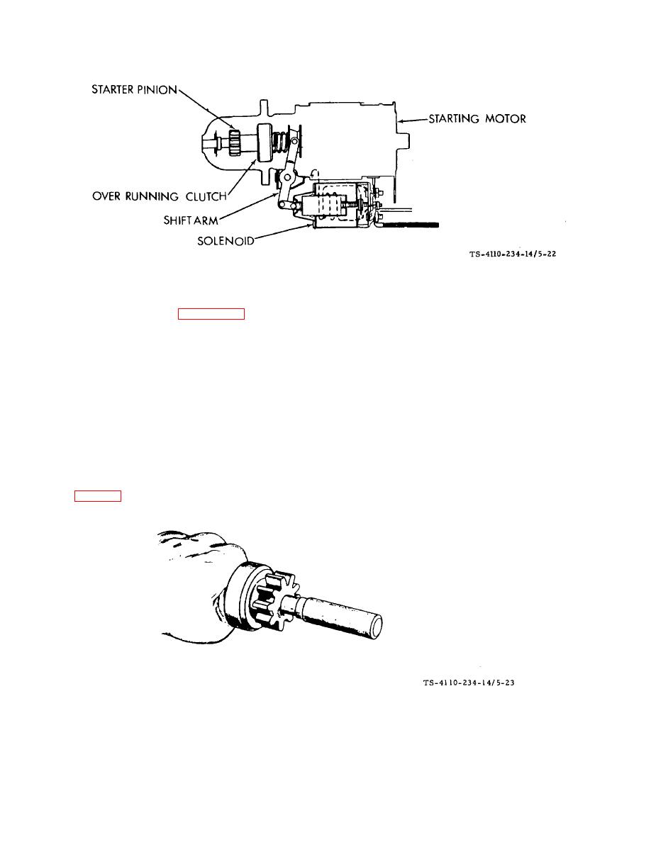
Figure 5-22. Solenoid Shift Starter F10000RG-2 |
|
||
| ||||||||||
|
|
 TM5-4110-234-14
TO 40R7-5-7-1
Figure 5-22. Solenoid Shift Starter F10000RG-2
g.
Disassembly. See figure 5-20.
(1)
Tag and disconnect all wires to the starting unit.
(2)
Remove the solenoid (where applicable).
(3) Remove the starter motor thru-bolts and divide the starter into three main assemblies- the front bracket, the
housing and the rear bracket. The spacers on the solenoid starters are used for adjustment of the thrust gap of the
armature shaft and are located between the rear bracket and the commutator shaft.
(4) The armature can now be removed from the front bracket. Be careful not to miss the small steel washer
used in the end of the armature shaft. Remove the shift lever at the same time the armature is removed. The spring
holder, lever springs and retainer can be removed prior to the lever.
(5) Remove the ring after driving the pinion stopper toward the pinion gear using a cylindrical tool or a short piece
of pipe (fig. 5-23). Remove the overrunning clutch and the pinion stopper at the same time.
Figure 5-23. Tool for Driving Pinion Stopper F10000RG-2
5-44
|
|
Privacy Statement - Press Release - Copyright Information. - Contact Us |
