 |
|||
|
|
|||
|
Page Title:
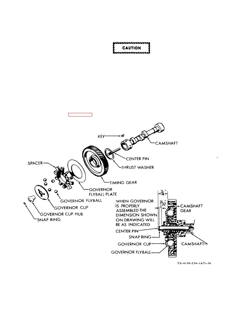
Figure 5-36. Camshaft and Governor Cup F10000RG-2 |
|
||
| ||||||||||
|
|
 TM5-4110-234-14
TO 40R7-5-7-1
(1)
After removing the flywheel key and mounting screws, tap the gear cover gently with a soft-faced hammer to
loosen it.
When installing the gear cover, make sure that the pin in the gear cover engages the
governor cup correctly.
(2) Turn the governor cup so that the metal lined hole is at the three o'clock position. The smooth side of the
governor yoke must ride against the governor cup.
(3) Turn the governor arm and shaft clockwise as far as possible and hold in this position until the gear cover is
installed flush against the crankcase. Be careful not to damage the gear cover oil seal.
(4)
Adjust the roll (stop) pin to protrude to a point 3/4 inch (1.91 cm) from the cover mounting surface.
c.
Governor Cup. See figure 5-36.
Figure 5-36. Camshaft and Governor Cup F10000RG-2
5-52
|
|
Privacy Statement - Press Release - Copyright Information. - Contact Us |
