 |
|||
|
|
|||
|
Page Title:
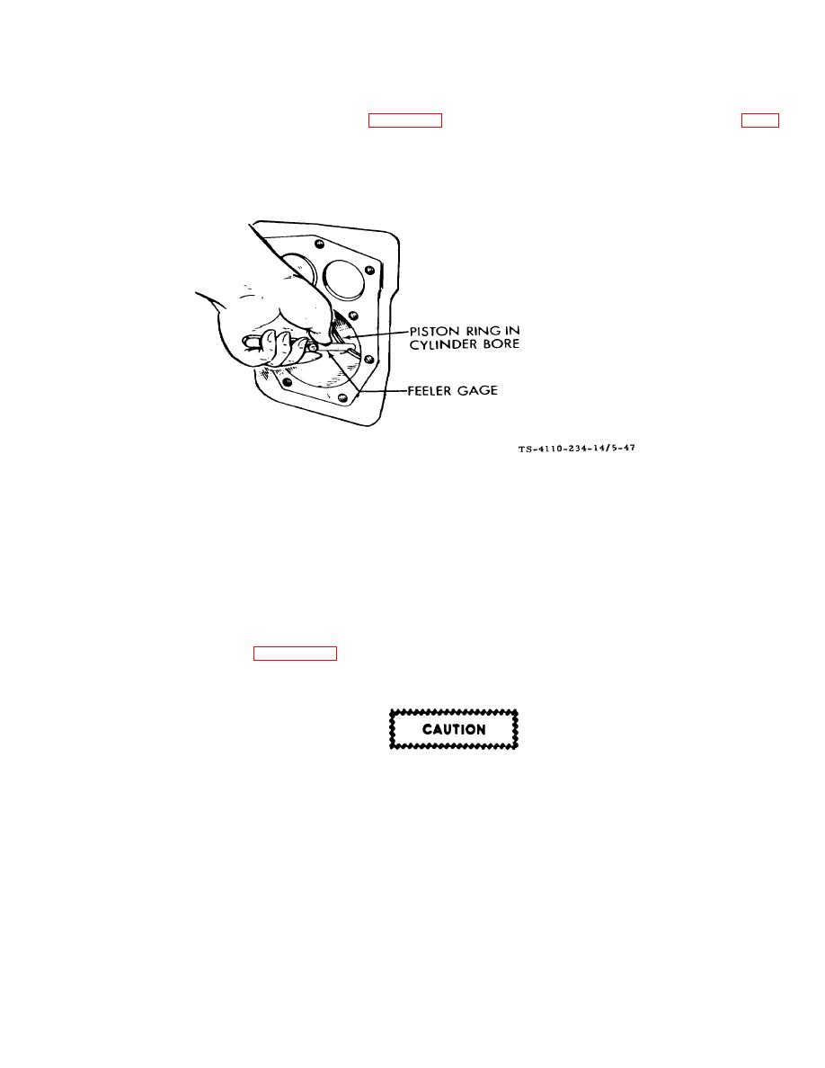
Figure 5-47. Fitting Piston Rings to Cylinder F10000RG-2 |
|
||
| ||||||||||
|
|
 TM5-4110-234-14
TO 40R7-5-7-1
(10) Before installing new rings on the piston, check the ring gap by placing each ring squarely in its cylinder at a
position corresponding to the bottom of its travel. See figure 5-47. The gap between the ends of the ring is given in Table
5-3. Rings which are slightly oversize may be filed as necessary to obtain the correct gap, but do not use rings which
require too much filing. Standard size rings may be used on 0.005-inch (0-127 mm) oversize pistons. Other oversize rings
must be used with corresponding oversize pistons. Rings of the tapered type are usually marked top on one side, or
identified in some other manner and the ring must be installed with this mark toward the closed end of the piston.
Figure 5-47. Fitting Piston Rings to Cylinder F10000RG-2
(11) Space each ring gap one third of the way around the piston from the preceding one, with no gap directly in
line with the piston pin. The bottom piston ring groove should be fitted with an expander and an oil control ring and the two
upper grooves fitted with compression rings. If a chrome faced ring is used, it will be in the top groove. The oil control ring
is selected for best performance in regard to the correct unit pressure characteristics.
(12) The piston is fitted with a full-floating type piston pin. The pin is kept in place by two lock rings in the piston,
one at each side. Be sure these lock rings are properly in place before installing the piston and connecting rod in the
engine. Refer to Table 53 for the correct piston-to-cylinder clearance.
b. Connecting Rods. See figure 5-42.
(1) The connecting rods should be serviced at the same time the pistons or rods are serviced. Rods must be
removed with the piston.
Make certain that all parts are marked or identified so that they are reinstalled in their
original positions.
(2) Proper clearance is obtained by replacing the pin bushing and the bearings. The rod bearings are precision
size and require no reaming.
(3) Install the connecting rods and caps with raised lined (witness marks) alined and with the caps facing toward
the oil base. The rod and cap numbered 2 fits on the crankshaft journal nearest the bearing plate. Coat the crankshaft
journal bearing surfaces with oil before installing the rods. Crank the engine by hand to see that the rods are free. If
necessary, rap the connecting rod cap screws sharply with a soft-faced hammer to set the rod square on the journal.
5-61
|
|
Privacy Statement - Press Release - Copyright Information. - Contact Us |
