 |
|||
|
|
|||
|
Page Title:
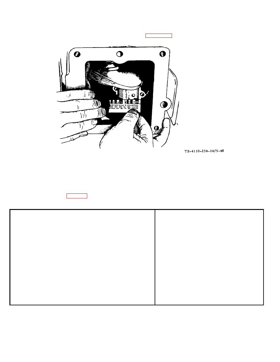
Figure 5-48. Measuring Bearing Clearance with Plasti-Gage F10000RG-2 |
|
||
| ||||||||||
|
|
 TM5-4110-234-14
TO 40R7-5-7-1
(4)
Checking Bearing Clearance with Plasti-Gage. See figure 5-48.
Figure 5-48. Measuring Bearing Clearance with Plasti-Gage F10000RG-2
(a) Place a piece of correct size Plasti-Gage in the bearing cap the full width of the bearing insert about 1/4 inch
(6.35 mm) off center.
(b) Rotate the crank about 30 degrees from bottom dead center and reinstall the bearing cap. Tighten the bolts
to the torque specified in Table 5-4. Do not turn the crankshaft.
Table 5-4. Engine Assembly Torques
LB.-FT.
Nm
Blower Housing Screws...............................................................
8-10
(10.9-13.6)
Connecting Rod Bolts..................................................................
27-20
(36.6-39.3)
Cylinder Head Screws .................................................................
29-31
(39.3-42.0)
Exhaust Manifold Screws ............................................................
15-20
(20.3-27.1)
Flywheel Mounting Screws..........................................................
35-40
(47.5-54.2)
Fuel Pump Mounting Screws ......................................................
5-6
(6.8-8.1)
Intake Manifold Screws ...............................................................
15-20
(20.3-27.1)
Oil Base ......................................................................................
43-48
(58.3-65.1)
Oil Pump Mounting Screws .........................................................
7-9
(9.5-12.2)
Rear Bearing Plate Capscrews ...................................................
20-25
(27.1-33.9)
Spark Plugs .................................................................................
25-30
(33.9-40.7)
Timing Gear Cover Screws .........................................................
10-13
(13.6-17.6)
Valve Cover Nut ..........................................................................
4-8
(5.4-10.9)
Magneto Stator Screws ...............................................................
15-20
(20.3-27.1)
Starter Mounting Bolts .................................................................
25-28
(33.9-37.9)
(c) Remove the bearing cap. Leave the flattened Plasti-Gage on the part to which it has adhered and compare
the widest point with the graduations on the Plasti-Gage envelope to determine bearing clearance.
5-62
|
|
Privacy Statement - Press Release - Copyright Information. - Contact Us |
