 |
|||
|
|
|||
|
Page Title:
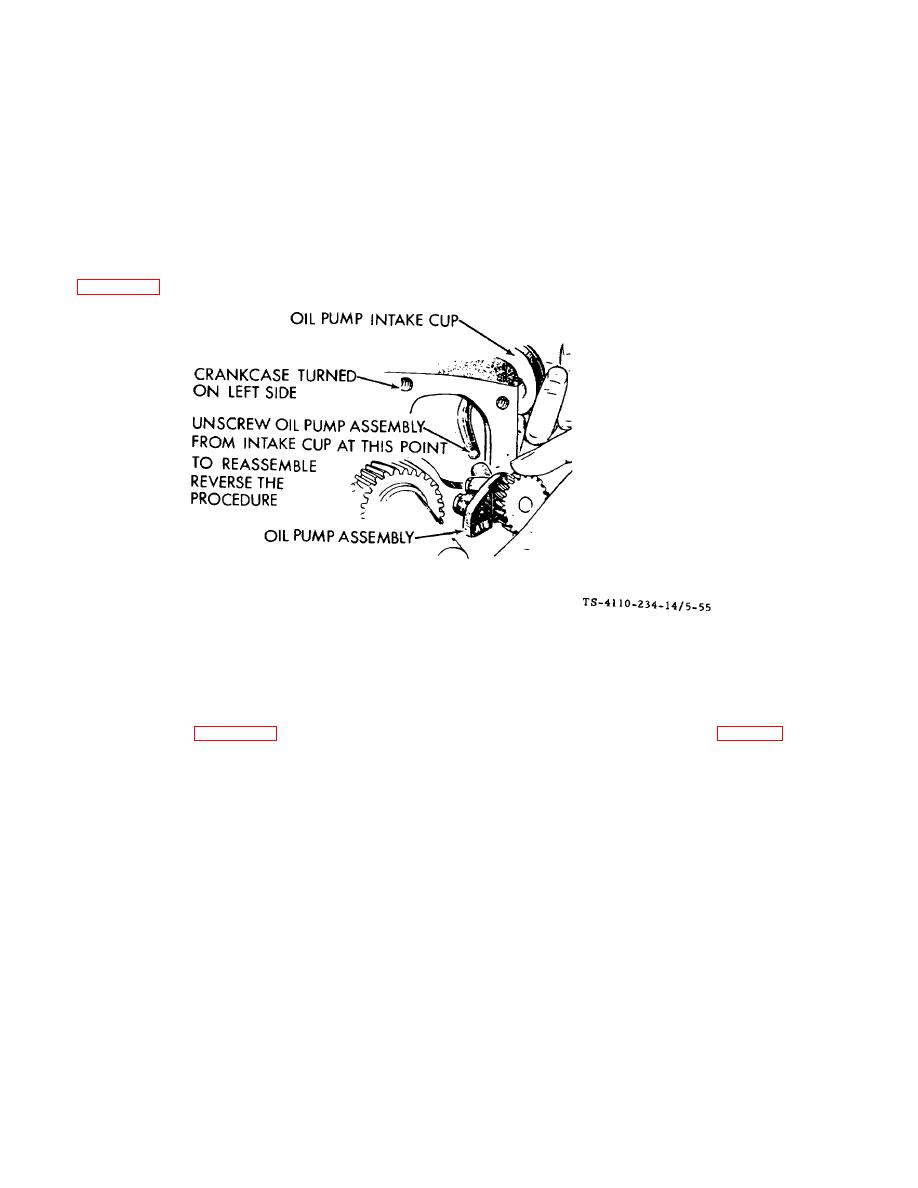
Figure 5-55. Oil Pump Disassembly F10000RG-2 |
|
||
| ||||||||||
|
|
 TM5-4110-234-14
TO 40R7-5-7-1
b. Oil Pump. The oil pump is mounted on the front of the crankcase behind the gear cover and is driven by the
crankshaft gear. The inlet pipe and screen assembly is attached directly to the pump body. A discharge passage in the
cover of the pump registers with a drilled passage in the crankcase. Parallel passages distribute oil to the front main
bearing, rear main bearing and pressure control bypass valve. Circumferential grooves in the main bearings supply oil to
the connecting rod bearings through drilled passages from each main journal. A drilled passage connects the front main
bearing oil supply to the front camshaft bearing. The flyball governor is lubricated by a drilled passage in the front camshaft
journal. The oil overflow from the bypass valve furnishes lubrication to the camshaft drive gears.
(1)
Check the oil pump thoroughly for worn parts. Oil the pump to prime it before reinstalling. Except for gaskets
and suction cup, the component parts of the pump are not available individually. Install a new pump assembly if required.
See figure 5-55.
Figure 5-55. Oil Pump Disassembly F10000RG-2
(2)
If new oil pump gaskets are installed, they should be the same thickness as those removed. c. Oil Bypass
Valve Inspection. See figure 5-56. The bypass valve (located to the right and behind the gear cover (fig. 5-54) controls oil
pressure by allowing excess oil to flow directly back to the crankcase. Normally the valve begins to open about 30 psi. The
valve is non-adjustable and normally needs no maintenance. To determine if abnormal (high or low) oil pressure is caused
by a sticky plunger inspect as follows:
(1)
Remove 3/8" - 24 x 3/4 inch cap screw located behind gear cover and under governor arm.
(2)
Remove spring and plunger with a magnet tool. Clean plunger and spring with a suitable solvent and reinstall.
d. Oil Bypass Valve Removal. To remove the valve, unscrew the recessed plug in the rear bearing plate and lift out the
spring and plunger assembly. Determine proper valve operation by checking the spring and plunger according to the
following measurements:
Plunger Diameter ..... ............................................................................................................................... 0.3365" to 0.3380"
(8.55 to 8.59 mm)
Spring
Free Length ......... .............................................................................................................................. 2-5/16" (58.74 mm)
22.225 (1.0 kg). 11 lb. (49.9g) at 1-3/16" (30.16 mm)
5-68
|
|
Privacy Statement - Press Release - Copyright Information. - Contact Us |
