 |
|||
|
|
|||
|
Page Title:
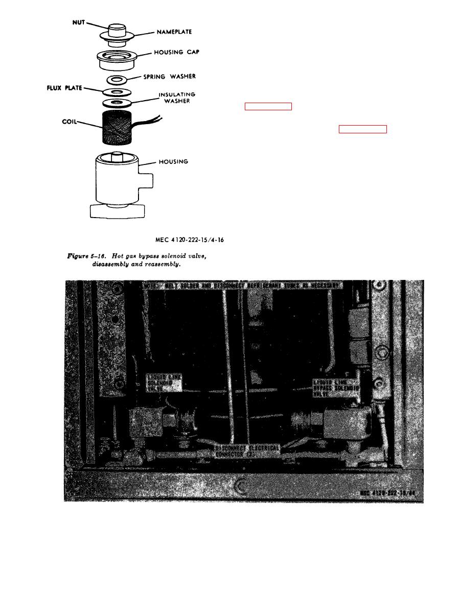
Figure 5-17. Liquid line solenoid valve, removal and installation. |
|
||
| ||||||||||
|
|
 tested. Wipe the soap solution from all joints and
mark any spot where a leak occurs. Drain the re-
frigerant system and repair lead and pressure
test.
service valve and discharge the refrigerant into a
safe area.
c. Pressure testing and evacuating. Refer to
refrigerant system.
charge the refrigerant system.
NOTE: To install charge hoses, remove condenser fan
and outside air thermostat Insert hoses through the
thermostat hole. Attach hoses to service valves. Install
fan prior to operation. Capacity of refrigeration system
is 3.7 pounds refrigerant-22, FSN 6830-174-9677.
AGO
22053A
53
|
|
Privacy Statement - Press Release - Copyright Information. - Contact Us |
