|
| |
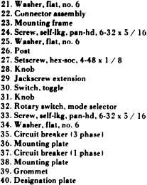
KEY for figure 6-5:
b. Disassembly. Refer to figure 6-5 and
disassemble the control module as follows:
(1) Remove four screws ( 1 ) and split grommet
(3). Slide cover (2) from module and pull capillary
tube and bulb through opening in bottom of cover.
(2) Remove knob (4). Drive out roll pin (5).
(3) Disconnect leads. Remove three self-
locking screws (6) and remove rear mounting frame
(23) with connector and temperature control switch
attached.
(4) Remove connector mounting screw (7),
nut (8), loop clamp (10), washer (21 ) and spacer
post (9) to release temperature control capillary
tube.
(5) Remove four screws (11), nuts (12), and
washers (13) and remove temperature control
switch (14).
(6) Remove screw ( 15), nut (16), lock washer
(17) and two flat washers ( 18) and disconnect
ground lead.
(7) Remove seven remaining screws (19),
nuts (20) and washers (21) and remove connector
assembly (22) from mounting frame (23). Do not
remove leads from connector unless they require
replacement.
(8) Remove three screws (24), washers (25)
and posts (26).
(9) Remove setscrew (27), knob (28), and
jack screw extension (29).
(10) remove toggle switch (30) by removing
locknut and washer.
(11) Remove mode selector knob (31), switch
nut and washer and remove mode selector rotary
switch (32).
( 12) Disassemble handle of three phase circuit
breaker (35) or single phase circuit breaker (37).
Remove six screws (33) and washers (34) securing
three phase circuit breaker (35) to mounting plate
(36) or four screws and washers securing single
phase circuit breaker (37) to mounting plate (38).
Remove circuit breaker.
( 13) Remove grommets (39) and designation
plate (40) from mounting plate.
c. Cleaning, Inspection and Repair.
(1) Clean metal parts with cleaning solvent
(Fed. Spec. P-D-680). Wipe off electrical parts
with a clean cloth.
(2) Refer to paragraph 4-45 and test switches
and circuit breaker. Replace defective parts.
(3) Inspect connector for damaged casing and
bent or broken contacts. Check wiring for damaged
insulation and broken wires. Check terminals for
damage. Repair damaged wiring. Replace con-
nector if defective.
(4) Check cover, frame and plates for bent
condition. Straighten bent parts or replace parts as
required.
d. Assembly. Refer to figure 6-5 and assemble
control module as follows:
(1) Place designation plate (40) on mounting
plate (36 or 38) and install circuit breaker (35 or
37) with screws (33) and washers (34). Install
grommets (39).
(2) Install rotary switch (32) and secure with
switch nut and washer. Install knob (31 ).
(3) Install toggle switch (30) and secure with
switch nut and washer.
(4) Insert jackscrew extension (29) through
opening in mounting plate and install knob (28)
and setscrew (27).
(5) Install connector assembly (22) on rear
mounting frame {23) and secure with seven screws
(19), nuts (20), and washers (21). Omit screw in
lower corner.
6-11
|