|
| |
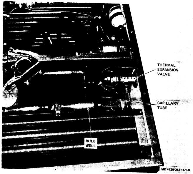
Figure 5-9. Thermal expansion valve.
c. Installation. Install thermal expansion valve
(fig. 5-9) as follows:
(1) Solder valve to tubing.
(2) Insert approximately one ounce of thermal
mastic in bulb well. Insert sensing bulb of ex-
pansion valve and move bulb back and forth to
distribute mastic and set bulb approximately one
inch beyond open end.
(3) Install housing top covers (para 4-21).
(4) Refer to paragraph 6-3 and charge the
refrigerant system.
5-29. Quench Thermal Expansion Valve
a. General. The quench thermal expansion valve
is hermetically sealed and cannot be repaired.
b. Removal. Remove the quench valve as
follows :
( 1 ) Refer to paragraph 6-3 and discharge the
refrigerant system.
(2) Remove housing rear top cover (para 4-
21).
(2) Soften mastic in bulb well (fig. 5-10) and
remove bulb from well. Take care to prevent
damage to capillary tube.
(4) Remove two screws, spacers, self-locking
nuts, and valve mounting brackets.
(5) Unsolder valve from tubing.
5-14
|