|
| |
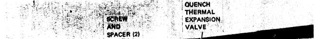
Figure 5-10. Quench valve and vibration eliminator.
c. Installation. Install the quench thermal ex-
pansion valve (fig. 5-10) as follows:
(1) Solder valve to tubing.
(2) Install mounting bracket and two screws,
spacers and self-locking nuts.
(3) Insert approximately one ounce of thermal
mastic in bulb well. Insert sensing bulb of ex-
pansion valve and move bulb back and forth to
distribute mastic and set bulb approximately one
inch beyond open end.
(4) Install housing rear top cover (para 4-21).
(5) Refer to paragraph 6-3 and charge the
refrigerant system.
5-30. Vibration Eliminators
a. Removal. Refer to paragraph 6-3 and
discharge the refrigerant system. Remove housing
top covers. Refer to figure 5-10 and unsolder hose
type vibration eliminators.
b. Installation. Refer to figure 5-10 and solder
vibration eliminators into refrigeration lines. Install
housing top covers. Refer to paragraph 6-3 and
charge the refrigerant system.
5-31. Pressure Regulator Valves
a. Removal. Refer to paragraph 6-3 and
discharge the refrigerant system. Remove housing
top covers (para 4-21). Refer to figure 5-11 and
remove screws, lock washers, loop clamps, and
spacers. Unsolder pressure regulator valves from
tubing.
b. Installation. Solder pressure regulator valve
(fig. 5-10) on tubing and install loop clamp, spacer,
screw and lock washer. Install housing top covers
(para 4-21). Refer to paragraph 6-3 and charge the
refrigerant system.
5-15
|