|
| |
C H A P T E R 6
REPAIR INSTRUCTIONS
Section I.
REFRIGERATION SYSTEM
6-1. General
The refrigerant system, illustrated by the
refrigerant flow diagram (fig. 5-1), is a mechanical,
vapor cycle-type circuit consisting of the
evaporator, thermal expansion valve, motor
compressor, condenser and the necessary valves
and cutout devices for automatic control during
operation. The thermal expansion valve releases
high-pressure liquid refrigerant into the evaporator
at reduced pressure. The liquid refrigerant begins
to vaporize by absorbing heat from the air passing
over the external surface of the evaporator core.
The heated vapor is sucked out of the evaporator
suction by the motor compressor and forced into
the condenser section under high pressure where it
is cooled and condensed back into a liquid. The
heat released during condensation is carried off by
the condensing air stream. The liquid refrigerant
flows from the condenser to a receiver, to a sub-
cooler, and then to the thermal expansion valve. If
the temperature control switch (evaporator return
air thermostat ) becomes satisfied, or the evaporator
return air temperature is lower than the control
switch set point, the refrigerant system will switch
to a by-pass condition. The temperature control
switch will activate the normally open bypass
solenoid valve, closing the valve, and therefore
shutting off the evaporator section of the unit. The
motor compressor will continue to pump as usual
and the suction pressure will begin to drop. When it
reaches approximately 65 psig, the pressure
regulating valves will start to open in an effort to
maintain the suction pressure above 55 psig
(approx.). As the suction temperature increases,
due to the pressure regulating valves opening, the
quench expansion valve will start to meter liquid
refrigerant into the suction line in an effort to
maintain the suction temperature below 75°F
(approx.) or 30° F superheat (approx.). This action
(the pressure regulating and quench valve actions)
is totally automatic and also may occur at extreme
conditions in an attempt to maintain the suction
pressures (even during the cooling mode) at a
condition above 55 psig and the suction tem-
peratures (measured at the quench bulb well)
below 75° F. When the compressor stops, the
equalizer solenoid valve de-energizes and assure es
its normal open position, thus allowing pressure to
equalize from the discharge line to the suction side
of the compressor. To determine if the valve is
good, check for continuity or ground, by using an
ohmmeter. It should read a resistance of 40 ohms.
The condenser louvers are operated by a refrigerant
powered piston located in high pressure part of the
system. This piston should be fully extended
(louvers open 80° approx.) at 250 psig head
pressure and fully closed at 165 psig. Failure to
perform this function could result in icing of the
evaporator coil and / or cutout on the low pressure
cutout.
6-2. Pressure Testing the Refrigerant System
a. General. A pressure test will indicate whether
the air conditioner is operating at normal or ab-
normal pressures. When the air conditioner is not
operating at normal pressures, the cause should be
ascertained and corrected. Refer to table 5-1 for
troubleshooting chart.
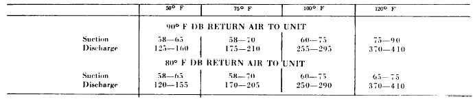
b. System Pressure Test. Remove caps from high
and low pressure charging valves (fig. 5-7). Correct
suction and discharge pressure gages to their
respective charging valves. Compare the gage
reading with the normal range of system pressure
shown in Table 6-1.
Table 6-1. Normal Operating Pressures
OUTDOOR AMBIENT — DEGREES F
6 - 1
|