|
| |
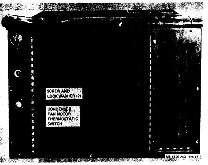
Figure 4-15. Condenser fan motor thermostatic switch.
d. Installation. Install the condenser fan ther-
mostatic switch as follows:
(1) Connect switch leads to connector.
(2) Refer to figure 4-15 and install switch in
opening. Secure switch with two screws and lock
washers.
(3) Connect electrical connector.
(4) Refer to paragraph 4-21 and install rear
top cover.
4-42. Fan Motor Capacitors
a. General. Single phase air conditioners are
quipped with fan motor run capacitors which are
located in the evaporator air inlet compartment.
b. Removal. Remove fan motor capacitors as
follows:
(1) Refer to paragraph 4-18 and remove the
evaporator air inlet louver.
(2) Refer to figure 4-16 and disconnect
capacitor leads.
(3) Remove two screws, lock washers and
straps from each capacitor. Remove capacitors
from air conditioner.
4-25
|