Order this information in Print

Order this information on CD-ROM

Download in PDF Format


Click here to make tpub.com your Home Page

Page Title: Figure 15. Damper Controls, Removal And Installation.
Back | Up | Next

Click here for a printable version

Google


Web
www.tpub.com

Home


Information Categories
.... Administration
Advancement
Aerographer
Automotive
Aviation
Combat
Construction
Diving
Draftsman
Engineering
Electronics
Food and Cooking
Math
Medical
Music
Nuclear Fundamentals
Photography
Religion
USMC
   
Products
  Educational CD-ROM's
Printed Manuals
Downloadable Books


T M    5 - 4 1 2 0 - 2 5 9 - 15 STEP   1. STEP   2. STEP  3. STEP   4. NOTE: NOTE: REMOVE   TOP   PANEL   (FIG.   13). 
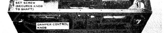
REMOVE   SET   SCREW   FROM   DAMPER   CONTROL   KNOB   AND REMOVE   KNOB   AND   RETAINER   NUT   FROM   THE   CONTROL MECHANISM. 
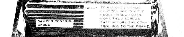
PUSH   CONTROL   MECHANISM   THROUGH   HOLE   IN   DAMPER CONTROL    BOX. 
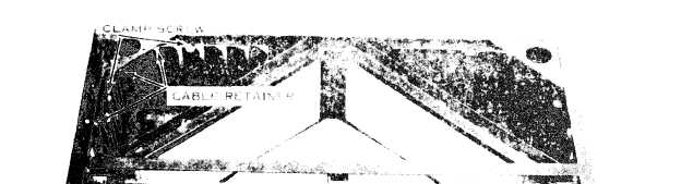
LOOSEN   THE   3   CABLE   RETAINERS   AND   2   CLAMP   SCREWS. AND   REMOVE   DAMPER   CONTROL   CABLE   FROM   UNIT. INSTALL   DAMPER   CONTROLS   IN   REVERSE   ORDER   OF   STEPS ABOVE. REMOVE   AND   INSTALL   OTHER   DAMPER   CONTROL IN   SAME   MANNER. ON   INSTALLATION,   CONNECT   CABLE   SO   THAT,   WITH   CONTROL- KNOB   AT   MINIMUM,   FRESH   AIR   DAMPER   IS   FULLY   CLOSED AND   RETURN-AIR   DAMPER   IS   FULLY   OPEN. ( V I C E - V E R SA WHEN   CONTROL   KNOB   IS   AT   MAXIMUM.) Figure   15.   Damper   Controls,   Removal   And   Installation. Section  VIII.  EVAPORATOR  AND  CONDENSER  FANS  AND  MOTORS 56.   General structions   for   the   evaporator   fans This   section   contains   the   maintenance   in- and  the  condenser  fans  and  motor. and   motor 25

Privacy Statement - Press Release - Copyright Information. - Contact Us - Support Integrated Publishing

Integrated Publishing, Inc. - A (SDVOSB) Service Disabled Veteran Owned Small Business