Order this information in Print

Order this information on CD-ROM

Download in PDF Format


Click here to make tpub.com your Home Page

Page Title: Figure 29. Expansion Valve, Adjustment, Removal And Installation
Back | Up | Next

Click here for a printable version

Google


Web
www.tpub.com

Home


Information Categories
.... Administration
Advancement
Aerographer
Automotive
Aviation
Combat
Construction
Diving
Draftsman
Engineering
Electronics
Food and Cooking
Math
Medical
Music
Nuclear Fundamentals
Photography
Religion
USMC
   
Products
  Educational CD-ROM's
Printed Manuals
Downloadable Books


TM 5-4120-259-15 REMOVAL STEP   1. STEP   2. STEP  3. STEP   4. INSTALL REMOVE   RIGHT   SIDE   PANEL   (FIG.   13). DISCHARGE   REFRIGERANT   (PAR. 94)   AND   OBSERVING   PARAGRAPH   96,   UNBRAZE   THE VALVE   AT   JOINTS. DISCONNECT   EXPANSION   VALVE   BULB   FROM   SUCTION   LINE   TuBING   BY   REMOVING   TAPE UNBRAZE     DISTRIBUTOR. NEW   VALVE   IN   REVERSE   ORDER. ST   THE   VALVE   BY   REMOVNG   THE   CAP   AND   TURNING   THE   SLOTTED   ADJUSTMENT   STEM. TURN   COUNTERCLOCKWISE   TO   INCREASE   FLOW   AND   LOWER   EVAPORATOR   TEMPER- ATURE. OPPOSITE   MOVEMENT   WILL   GIVE   OPPOSITE   RESULTS.   TURN   NO   MORE   THAN TWO   TURNS   AT   A   TIME. ALLOW    ABOUT    30    MINUTES    FOR    BALANCE    TO    TAKE    PLACE AFTER   EACH   ADJUSTMENT. 
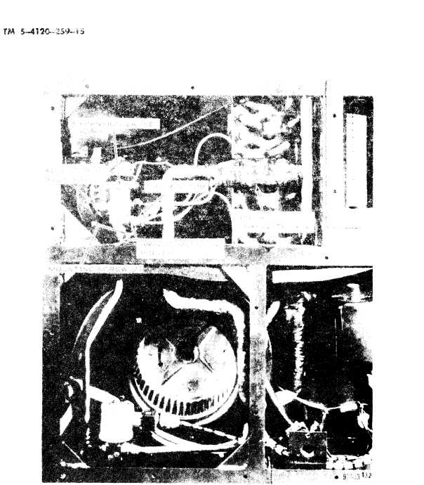
Figure   29.   Expansion   Valve,   Adjustment,   Removal   And   Installation. 44

Privacy Statement - Press Release - Copyright Information. - Contact Us - Support Integrated Publishing

Integrated Publishing, Inc. - A (SDVOSB) Service Disabled Veteran Owned Small Business