Order this information in Print

Order this information on CD-ROM

Download in PDF Format


Click here to make tpub.com your Home Page

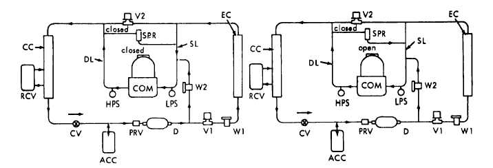
Page Title: Figure 5-1. Refrigerant flow diagram
Back | Up | Next

Click here for a printable version

Google


Web
www.tpub.com

Home


Information Categories
.... Administration
Advancement
Aerographer
Automotive
Aviation
Combat
Construction
Diving
Draftsman
Engineering
Electronics
Food and Cooking
Math
Medical
Music
Nuclear Fundamentals
Photography
Religion
USMC
   
Products
  Educational CD-ROM's
Printed Manuals
Downloadable Books


TM 5-4120-270-15 A. COOLING CYCLE OF OPERATION DEVICE LEGEND ACC ACCUMULATOR (2) CC CONDENSER COIL COM COMPRESSOR CV CHECK VALVE D DEHYDRATOR DL DISCHARGE LINE EC EVAPORATOR COIL HPS HIGH PRESSURE CUTOUT SWITCH LPS LOW PRESSURE CUTOUT SWITCH B.  BYPASS CYCLE OF OPERATION PRV PRESSURE RELIEF VALVE RCV RECEIVER SL SUCTION LINE SPR SUCTION PRESSURE REGULATOR VALVE V1 LIQUID LINE SOLENOID VALVE V2 HOT GAS BYPASS SOLENOID VALVE W1 EVAPORATOR FEED THERMAL EXPANSION VALVE W2   BYPASS THERMAL EXPANSION VALVE Figure 5-1.  Refrigerant flow diagram Figure 5-2.  Control panel and junction box, removal and installation 5-5

Privacy Statement - Press Release - Copyright Information. - Contact Us - Support Integrated Publishing

Integrated Publishing, Inc. - A (SDVOSB) Service Disabled Veteran Owned Small Business