|
| |
TM 5-4120-270-15
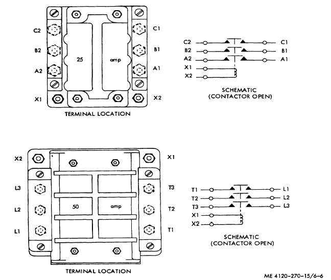
Figure 6-6. Magnetic contactor test points
(1) Disconnect receptacle connector from
motor junction box.
(2) Test continuity across each combination of
two motor terminals. Lack of continuity indicates an
open winding.
(3) Place one contact of the tester against
motor housing and the other against the motor terminals
one at a time. If a circuit is indicated, the motor is
grounded.
(4) Test the motor stator for insulation
resistance as instructed in TM 5-764 (Electric Motor and
Generator Repair). The insulation resistance should
measure not less than 0.5 megohms for the motor on
either model.
Note. The resistance measurement should be used only
as a general guide, taking into consideration the
accuracy of the instrument used, test lead resistance,
and ambient temperature at time of test. If more precise
measurement is required, an instrument such as a Kelvin
or Wheatstone bridge should be used, or comparative
measurement between the suspected component and a
like item to be good should be utilized. In all cases
where a megohmmeter is used for testing, make certain
that the unit is thoroughly dry. Wet condemnation
tolerances should be considered.
(5) Connect the air conditioner to a proper
source of power. Use a hook-type ammeter and read
the amperage flowing in each of the evaporator fan
motor leads. On model MAC4V60-360- the ammeter
should indicate between 5.75
6-7
|