|
| |
TM 5-4120-270-15
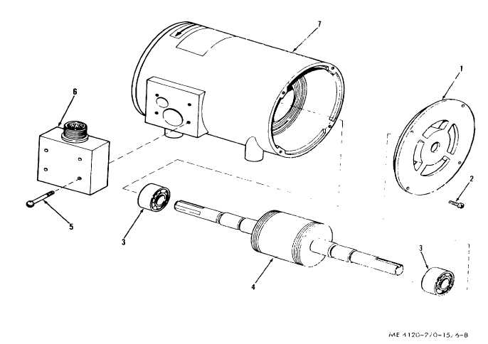
Key to fig. 6-8:
2 Screw, machine
4 Rotor and shafts
6 Box, connector
1 Cover, end
3 Bearing, ball
5 Screw, machine
7 Frame and windings
Figure 6-8. Evaporator fan motor, exploded ,view.
b. Removal. Refer to figure 5-3 and remove the
heater high temperature cutout.
c. Disassembly. Disconnect electrical leads from
heater high ’temperature control. Do not disassemble
further.
d. Testing. Using a continuity tester or a multimeter
set on low OHMS range, test for continuity between each
pair of terminals. Replace heater high temperature
cutout
if
an
open
reading
is
obtained.
e. Reassembly. Connect electrical leads to heater high
temperature cutout.
f. Installation. Refer to figure 5-3 and install heater
high temperature cutout on beater support assembly.
6-12. Wiring Harness and Wire Leads
a. General. Tile electrical circuits in the air
conditioner are completed by individual wire leads or by
wire leads laced or enclosed in a in a loom to form a
6-9
|