|
| |
TM 5-4120-270-15
d. Removal. Discharge the refrigerant system (para
6-16) refer to figure 5-7, and remove the thermal
expansion valves.
e. Installation. Replace defective expansion valves
and install in reverse order of removal as illustrated in
figure 5-7. Evacuate and recharge the unit refrigerating
system (para 628, 29, 30).
6-18. Hot Gas Bypass Solenoid Valve
a. General. The hot gas bypass solenoid valve
is a normally open, pilot operated valve which remains
closed while the selector switch is on "COOL". The hot
gas bypass valve opens whenever the selector switch is
moved to another position, bypassing refrigerant gas
under pressure in the discharge line to the compressor
suction line. Moving the selector switch to "COOL"
permits the hot gas bypass valve to close after the 30
second delay provided by the time delay relay.
b. On-Equipment Testing.
(1) Start the air conditioner. If the valve clicks
closed, place hand on the downstream piping. If the
piping begins to cool immediately, the valve is operating
properly. Replace valve if it does not operate as
specified.
(2) If the hot gas bypass solenoid valve fails to
click closed after a 30-second delay, stop the unit
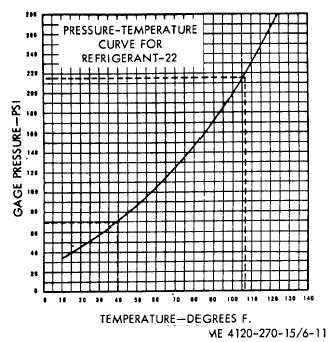
Figure 6-11. Pressure temperature curve for
Refrigerant-22.
and check the electrical connection and the solenoid coil.
(3) Refer to figure 5-8 and disconnect the
electrical plug connector. Test the solenoid control coil
at the electrical receptacle connector, placing a continuity
tester or a multimeter set on low OHM range, across
each pin. If continuity does not exist, remove valve and
repair or replace control coil.
(4) Using a multimeter set on high OHMS
range, measure resistance between one of the jack pins
and the air conditioner frame. If resistance reading is
less than 0.5 megohm, remove valve and repair or
replace control coil.
c. Removal and Disassembly. Discharge refrigerant
system (para 6-28), refer to figure 5-8 and remove and
disassemble the hot gas bypass solenoid valve.
Caution:
Disassemble
valve
before
attempting to remove tubing from valve to avoid
heat distortion of internal parts.
d. Reassembly and Installation. Replace any
defective parts. Reassemble valve and install in reverse
order of removal as illustrated on figure 5-8. Test,
evacuate and recharge the refrigerant system (para 6-
28, 29, 30).
6-19. Liquid Line Solenoid Valve
a. General. The liquid line solenoid valve is a
normally open pilot operated valve which automatically
closes and opens on command from the air conditioner
temperature control thermostat when the selector switch
is on "COOL" position. In the open position, the liquid
line solenoid valve allows flow of liquid refrigerant from
the condenser to the evaporator coil. In the closed
position, the liquid line solenoid valve blocks the flow of
liquid refrigerant to the evaporator coil.
b. On-Equipment Testing.
(1) Turn the temperature selector thermostat
5°-10°F below ambient temperature to assure refrigerant
system will operate on the cooling cycle. Start air
conditioner and place hand on the dowstream piping. If
the piping begins to warm immediately, the valve is
operating properly. Replace valve if it does not operate
as specified.
(2) Turn temperature control thermostat 5°-
10°F above ambient temperature to place refrigerant
system on bypass cycle. The liquid line solenoid valve
should immediately click closed. Place hand on the
downstream piping. If the piping begins to cool
immediately the valve is operating properly. Replace
valve if it does not operate as specified.
6-13
|