 |
|||
|
|
|||
|
Page Title:
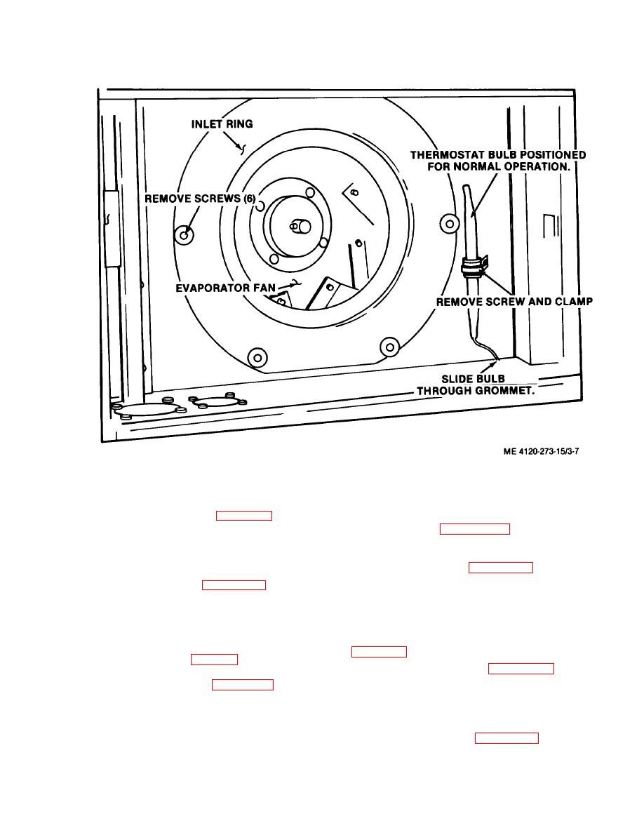
Figure 3-7. Evaporator fan, inlet ring and thermostat sensing bulb removal and Installation |
|
||
| ||||||||||
|
|
 TM 5-4120-273-15
installation.
motor.
top of the unit, figures 311 and 3-12. A fan
motor relay starts the fan motor and controls the
high and low speeds.
3-25. Capacitors (Model CV-6-1-15-60
only)
remove fan motor relay(s).
c. Inspection and Testing.
capacitors.
b. Inspection and Testing.
(1) Inspect for pitted or burned contacts.
(1) Inspect for cracked case and broken or
(2) Test for continuity across coil with mul-
damaged contacts.
timeter set on OHMS. Refer to wiring diagram
(2) Use a multimeter set on OHMS. Refer
to wiring diagram (fig. 1-5). A full reading
should be made with a steady return to zero.
and install relay(s).
capacitors.
CV-6-3-08-400 only)
3-26. Pan Motor Relays
Note. Model CV-6-1-15-60 has one fan motor relay.
diode surge protector.
Model CV-6-3-08-400 has two fan relays.
|
|
Privacy Statement - Press Release - Copyright Information. - Contact Us |
