 |
|||
|
|
|||
|
Page Title:
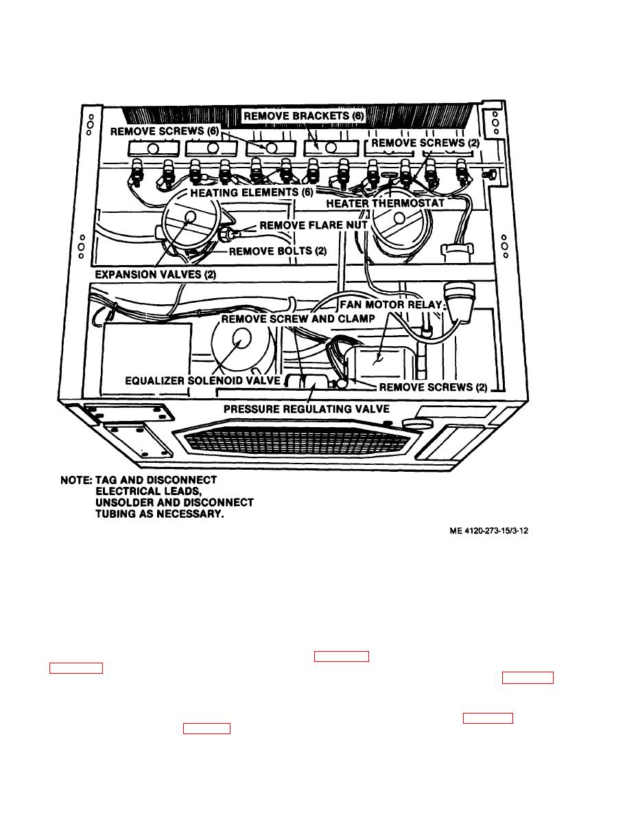
Figure 3-12. Model CV-6-1-15-60 heating element, expansion valve |
|
||
| ||||||||||
|
|
 TM 5-4120-273-15
Figure 3-12. Model CV-6-1-15-60 heating element, expansion valve; fan motor
relay, equalizer solenoid valve, pressure regulating valve, heater thermostat, removal
and installation.
b. Inspection and Testing.
b. Inspection and Testing.
(1) Inspect for broken or damaged leads and
(1) Inspect for broken or damaged leads and
kinked or broken capillary tubing.
kinked or broken capillary tubing.
(2) Test for continuity across switch with
(2) Test for continuity across switch with
multimeter set on OHMS. Refer to wiring diagram
multimeter set on OHMS. Refer to wiring diagram
a. Inspect
for broken or damaged contacts.
a. General. The low pressure switch prevents
b. Test for
continuity with multimeter set on
the compressor from operating if the suction pres-
OHMS. Refer
to wiring diagram figure 1-5 to es-
sure drops below 25 psig (fig. 3-14).
tablish points
of continuity.
|
|
Privacy Statement - Press Release - Copyright Information. - Contact Us |
