 |
|||
|
|
|||
|
Page Title:
Section III. REMOVAL AND INSTALLATION OF MAJOR COMPONENTS OR AUXILIARIES |
|
||
| ||||||||||
|
|
 TM 5-4120-273-15
5-14. High Crankcase Temperature
5-10. Compressor Noisy
Probable cause
Possible remedy
Possible remedy
Probable cause
Excessive superheat ---------Reset expansion valve
Replace compressor
Insufficient clearance
(para 5-17).
between rotating com-
Liquid line filter clogged -----Replace filter (fig. 3-3).
pressor parts
Bearings worn -----------------Replace compressor (para
5-15. Little or no Heating Capacity
Probable cause
Possible remedy
Slugging due to floodback Check setting of expansion
Wiring and wiring harness Replace wire or wiring
valve. Check thermal
of refrigerant
harness (para 5-22).
defective
bulb.
5-11. Hissing
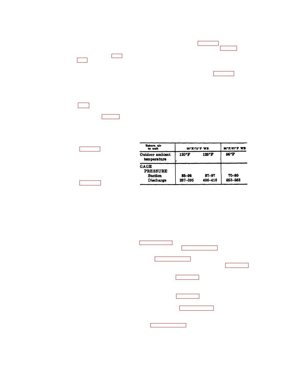
If the system is losing cooling capacity, or is in
Probable cause
Possible remedy
some way not functioning properly, a check of sys-
Insufficient refrigerant
Add refrigerant (para
tem operating pressure will frequently lead to
flow through expansion
cause of malfunction. Install pressure gages on
valves
access fittings of suction and discharge lines and
Clogged liquid line filter ----------Clean filter (pars 3-9b).
expose gages to system pressure. Compare gage
readings with normal ranges of systems pressures
5-12. Cold Compressor
listed in table 1.
Possible remedy
Probable cause
Table 5-1. Normal Operating Pressures.
Liquid carrying over from Check refrigerant charge
and expansion valves.
evaporator or through
quench valve
5-13. Cylinders and Crankcase Sweating
Probable cause
Possible remedy
Floodback ----------------Check refrigerant charge
and expansion valves.
Section III. REMOVAL AND INSTALLATION OF
MAJOR COMPONENTS OR AUXILIARIES
the system. Repeated burnouts will occur if all of
5-17. Compressor
the contaminants are not removed.
a. General The sole purpose of the compres-
b. Removal.
sor is to raise the pressure of refrigerant gas from
evaporator pressure to condensing pressure. The
(1) Remove front access panel, reference
function of the compressor is to deliver refriger-
trol box, reference paragraph 3-28.
ant to the condenser at a pressure and tempera-
ture at which the condensing process can readily
(2) Discharge refrigerant from system ref-
erence paragraph 5-21b.
be accomplished. The motor/compressor is a her-
metically sealed unit and is not repairable in the
(3) Remove condenser coil, reference para-
field. An inoperative compressor is usually due to
graph 6-5.
a mechanical failure causing the compressor to
(4) Refer to figure 3-6 and remove compres-
freeze, control failure, or a motor burnout. If the
sor through rear of unit.
motor/compressor is mechanically frozen or there
c. Installation.
has been a motor burnout, the compressor must
(1) Refer to figure 3-6 and install corn-
be removed and replaced. When the motor of a
pressor.
hermetic compressor fails, high temperatures may
develop within the compressor causing a break-
(2) Refer to paragraph 6-5 and install the
down of the oil and refrigerant, resulting in for-
condenser coil.
mation of acid, moisture, and sludge. All these
(3) Evacuate and recharge the unit, refer-
are extremely corrosive and must be flushed from
ence paragraph 5-21.
|
|
Privacy Statement - Press Release - Copyright Information. - Contact Us |
