 |
|||
|
|
|||
|
|
|||
| ||||||||||
|
|
 TM 5-4120-274-15
install electric heater thermostat.
a. Inspection. Inspect refrigerant piping for
kinking, holes and unsatisfactory welding.
b. Testing.
(1) Halide torch leak detector. The pre-
ferred method of field testing for leaks in the
refrigeration system is by using a halide torch.
Operate the air conditioner (fig. 2-3) and pass the
exploring tube slowly over all sweat fittings, me-
chanical couplings, and valves. If refrigerant is
leaking from the system the flame of the torch
will change from blue to green when the leak is
small. If the leak is large, the flame will be a
deep blue with a reddish tip or the flame may be
entirely extinguished.
(2) Soap solution method. Operate the air
conditioner (fig. 2-3). Brush all points of possi-
ble leakage with soap solution. Watch for bubbles.
Follow a definite sequence so that all joints will
be thoroughly tested. Wipe the solution from all
joints and mark any spot where leakage occurs.
installation.
automatically actuated by the thermostat and con-
3-43. Outside Air Thermostat
trols the flow of refrigerant to the evaporator
a. General. The outside air thermostat is
coil.
mounted to the rear housing of the air condition-
b. Inspection. Inspect for cracked or broken
er. It prevents the compressor from being started
casing and damaged or broken terminals.
when the outside temperature is below 50F. This
prevents the unit from being operated at a time
multimeter set on OHMS. Refer to wiring dia-
when low condensing and suction pressures will
gram figure 1-5 to establish points of continuity.
hamper system operation.
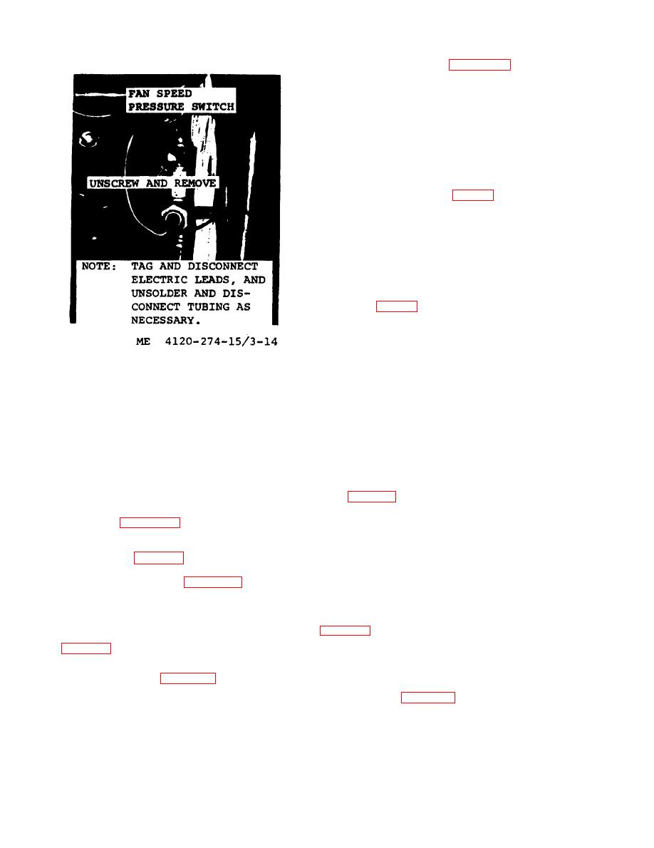
b. Removal. Remove outside air thermostat as
illustrate on figure 3-13.
c. Testing. Test the thermostat for continuity
with a multimeter set on OHMS. Refer to the
tuated by the on-off switch and serves to equal-
wiring diagram figure 1-5 for the points to estab-
ize system pressures during shutdown.
lish continuity.
b. Inspection. Inspect for cracked or broken
casing and damaged or broken terminals.
outside air thermostat.
multimeter set on OHMS. Refer to wiring diagram
a. General. The electric heater thermostat
overheating.
a. General. The two access fittings (suction
line and discharge line) provide access to the re-
move electrical heater thermostat.
frigerant system, figure 3-6.
c. Testing. Test for continuity with multimeter
b. Inspection. Inspect for cracked casing or
set on OHMS. Refer to wiring diagram figure
damaged threads.
1-5 to establish points of continuity.
|
|
Privacy Statement - Press Release - Copyright Information. - Contact Us |
