 |
|||
|
|
|||
|
|
|||
| ||||||||||
|
|
 TM 5-4120-274-15
the changing of the color code from green to yel-
3-49. Pressure Relief Valve
low.
a. General. Pressure relief valve (fig. 3-6) is
located on a tee just below the filter-drier. The
pressure relief valve protects the refrigerant sys-
Inspect for cracks or broken casing.
tem from excessive pressure.
b. Inspection. Inspect for cracked or broken
casing.
a. General. The evaporator coil is mounted on
the casing, directly behind the discharge grille.
The coil must be removed from the air conditioner
The evaporator pressure regulating valve figures
for repair or replacement. The mixture of fresh
3-10, 311 regulates refrigerant pressure in the
air and re-circulated air is passed through the
evaporator to prevent coil freeze up. The valve
evaporator coil and forced into the conditioned
is preset to establish a minimum pressure in the
air space by the evaporator fan.
evaporator of 58 psig.
with halide torch for refrigerant leaks.
c. Inspection and Cleaning.
a. General A 1-ton expansion valve controls
(1) Inspect coil for bent fins, cracks or
the rate of flow of liquid refrigerant into the evap-
breaks, solder any cracks. Straighten bent fins
orator coil during the cooling cycle of operation
with coil comb or thin nose pliers.
(2) Clean coil with low pressure, compressed
air.
is in tie bypass cycle of operation.
b. Inspection.
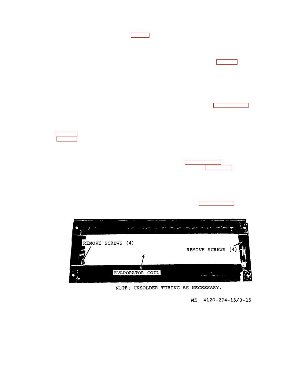
d. Removal.
(1) Check for loose or leaking connections.
(1) Remove top panel and discharge grille,
(2) Make sure the thermal bulb is securely
refer to paragraph 318.
fastened and is covered with rubber insulation.
(2) Refer to figure 3-15 and remove the
evaporator coil.
3-52. Sight Glass
e. Installation.
a. General. The sight glass indicates the refrig-
(1) Install the evaporator coil refer to fig-
erant is indicated by flash gas in sight glass (fig.
ure 3-15.
3-13).
(2) Install the top panel and discharge
b. Inspection. Inspect for excessive moisture
grille, refer to paragraph 3-18.
in refrigerant. Excessive moisture is indicated by
|
|
Privacy Statement - Press Release - Copyright Information. - Contact Us |
