 |
|||
|
|
|||
|
Page Title:
Connector Receptacles |
|
||
| ||||||||||
|
|
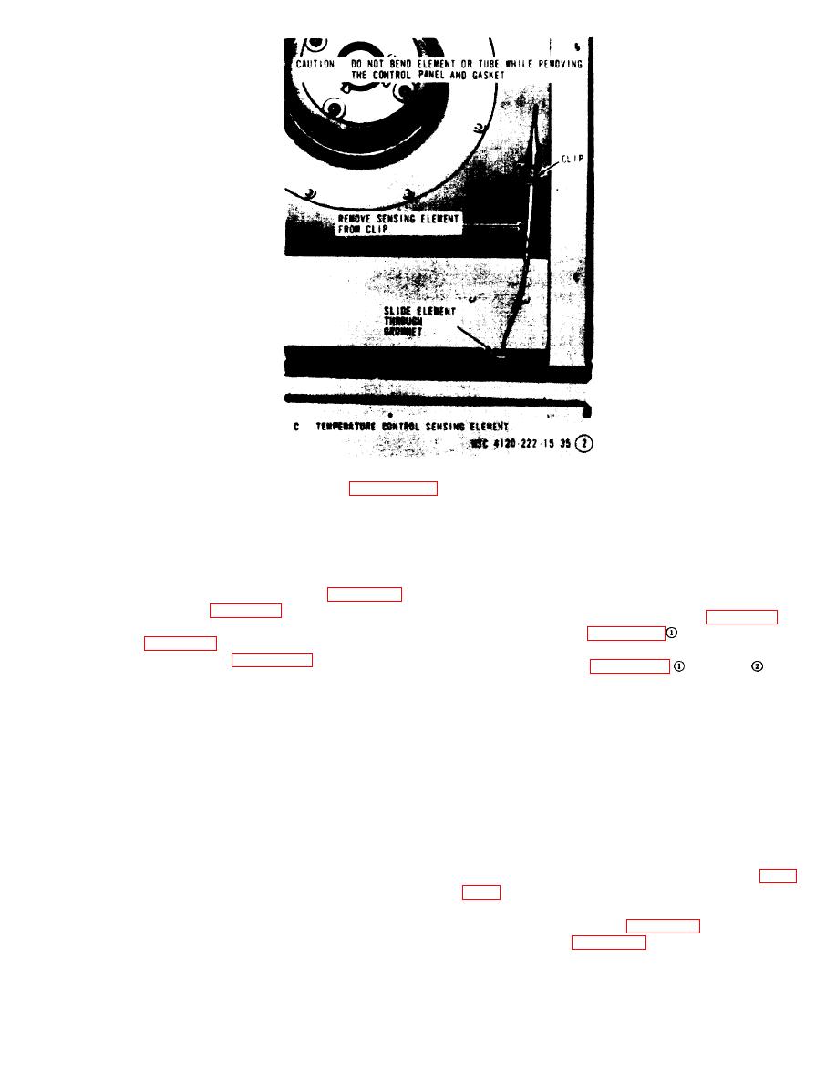 Figure 3-9 @-Continued.
motor assembly frame. Connect the other lead to
any of the three receptacle pins, no continuity
a. General. The control panel, housing the
should exist (0 reading).
selector switch and temperature control switch, is
b. Removal.
mounted on the control box.
(1) Remove the fan guard (para 3-17) and
b. Removal.
condenser fan (para 3-19).
(1) Remove front access panel (para 3-15).
(2) Remove the evaporator fan and inlet
and remove the
(2) Refer to figure 3-9
ring (para 3-18).
control box front panel.
(3) Refer to figure 3-8 and remove the
and 3-9
and
(3) Refer to figure 3-9
blower motor assembly.
remove the control panel.
c. Installation. Install the blower motor assem-
c. Installation. Install the control panel, control
bly, fans, and guards by reversing the order of
box panel, and front access panel by reversing
removal.
the order of removal.
3-25. Control Box Assembly
a. General. The control box houses the fuses,
The condenser receptacles are mounted on the
phase sequence relay, high pressure cutout
case with four screws. When any receptacle
switch, terminal blocks, circuit breaker, rectifier,
connector is moved to an alternate position, re-
evaporator heater contactor, and compressor con-
place the connector with the cover that was re-
tactor.
moved from the alternate position. When chang-
b. Removal.
ing the location of the receptacle connector be
(1) Remove the front access panel (para
certain that all leads to the receptacle are han-
dled with care and not pulled loose or damaged.
(2) Remove the control box front panel and
Remove the four mounting screws and ease the
control panel assembly (para 3-24).
leads around components in such manner as to as-
(3) Refer to figure 3-10 and remove the con-
sure clearances for future maintenance. Mount
trol box assembly.
the receptacle connector and cover assembly.
|
|
Privacy Statement - Press Release - Copyright Information. - Contact Us |
