 |
|||
|
|
|||
|
Page Title:
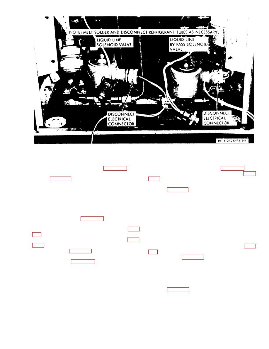
Figure 5-8. Liquid line solenoid valve and liquid line bypass solenoid valve, removal and installation. |
|
||
| ||||||||||
|
|
 removal and installation.
(2)
Replace the dehydrator (para 5-18).
(3) Replace the dehydrator (para 5-18).
(4) Evacuate and recharge the refrigerant
(3)
Replace the front access panel (para
system (para 6-1).
(4)
Evacuate and recharge the refrigerant
system
5-18. Dehydrator
a. On-Equipment Testing. Start the unit, if the
solenoid valve fails to click, upon start of opera-
a. General. The dehydrator prevents the accu-
tion, stop the unit and check the valve coil and
mulation of moisture and contaminants within
connections in the same manner as used for the
the refrigerant system. The dehydrator must be
hot gas bypass valve (para 5-16).
replaced each time the refrigerant system is ex-
b. Removal and Disassembly.
posed to the atmosphere during the replacement
(1) Discharge the refrigerant system (para
of a system component.
b. Removal.
(2) Remove the front access panel (para
(1) Remove the front access panel.
(2) Discharge the refrigerant system (para
(3) Refer to figure 5-8 and remove the liq-
uid line solenoid valves.
(3) Refer to figure 5-10 and remove the de-
(4) Refer to figure 5-9 and disassemble the
hydrator.
liquid line solenoid valves. Do not apply heat to
c. Installation.
assembled valve.
(1) Install the dehydrator and access panel
(5) Disconnect tubing from body.
by reversing the order of removal.
c. Reassembly.
(2) Evacuate and recharge the refrigerant
(1) Solder tubing to body.
system (para 6-1).
(2) Reassemble liquid line solenoid valves
by reversing the order of disassembly.
d. Installation.
immediately beneath the dehydrator, prevents ex-
(1) Install the liquid line solenoid valves by
cessive pressure in the refrigerant system.
reversing the order of removal.
|
|
Privacy Statement - Press Release - Copyright Information. - Contact Us |
