 |
|||
|
|
|||
|
Page Title:
Figure 6-3. Pressure temperature chart. |
|
||
| ||||||||||
|
|
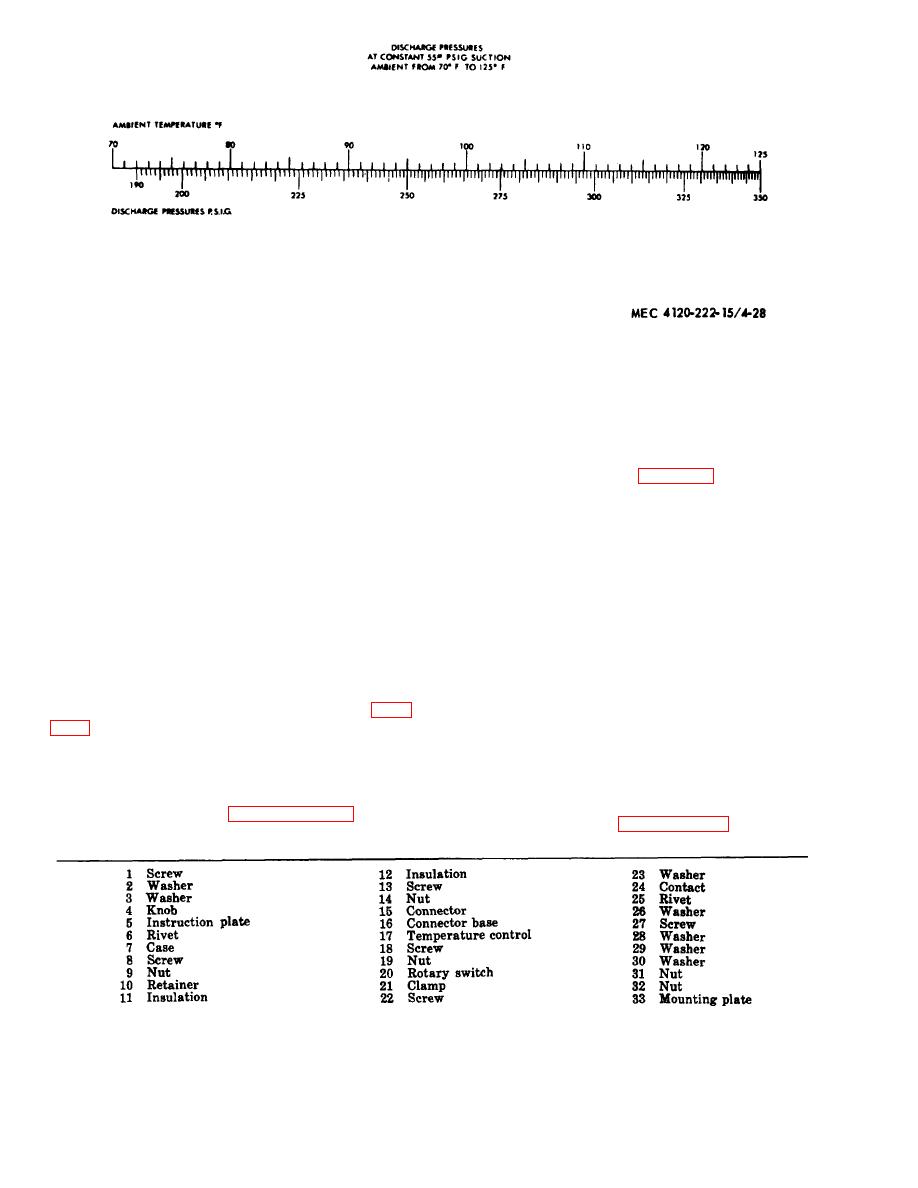 Figure 6-3. Pressure temperature chart.
6-2. Refrigerant Tubing
(6) Install condenser fan and grill (para
3-lo).
The refrigerant tubing used in the air condi-
(7) Open refrigerant drum shutoff valve.
tioner consists of copper tubing and the necessary
Start unit and weigh in 3.5 pounds of refrigerant
fittings. The joints of the refrigerant tubes are
R-22, Continue adding refrigerant until sight
soldered with silver solder (para 5-10f(3)). In-
glass indicates full.
spect the tubing and fittings for leaks, cracks,
breaks, or signs of excessive wear. Replace any
Note. Operate unit at COOL position during
defective tubing or fittings with material of the
charging operation. Partially block discharge grill with
same size, type, and shape. When applying heat
cardboard baffle. Adjust baffle until suction pressure gage
reads 55 psig pressure. Continue adjusting bathe until the
to the tubing close to a solenoid valve, direct the
discharge pressure corresponding to the ambient tempera-
heat away from the valve body. Keep flame away
ture is obtained.
from distributor of expansion valves. Test all
tubing repairs for leaks.
(8) Close service valves, close refrigerant
drum shutoff valve and stop the unit.
Note. If the refrigerant system has been exposed to
(9) Disconnect the pressure manifold from
the atmosphere by the removal of any tubing or a fitting,
replace the dehydrator and pressure test and evacuate the
the service valves. Replace valve caps.
system before recharging. When removing or replacing
(10) Inspect the compartment thoroughly
tubing, pass dry nitrogen through the lines to prevent cop-
and install the condenser fan and grill (para
per oxides.
Section II. CONTROL PANEL AND BLOWER MOTOR
b. Disassembly and Reassembly. Refer to figure
6-3. Control Panel
6-4 and disassemble the control panel.
move the control panel.
stall the control panel.
Figure 6-4--Continued.
|
|
Privacy Statement - Press Release - Copyright Information. - Contact Us |
