|
| |
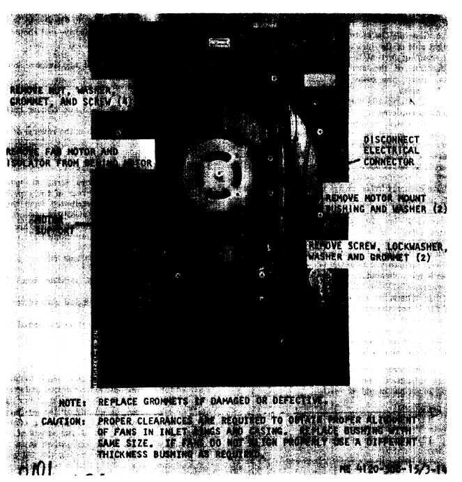
Figure 3-14. Fan motor, removal and replacement.
time. If continuity is indicated between any ter-
(3) Refer to paragraph 3–23 and remove t he
minal and the housing, the motor is defective and
evaporator fan.
must be replaced.
(4) Refer to figure 3-14 and remove the fan
(5) Check cold resistance tolerance at termi-
motor.
nals A and D, E and B, and F and C (fig. 1–4).
Resistance at each terminal should be 7.25 (±1)
c. Installation. Installation is the reverse of re-
moval.
ohm.
c. Removal
(1) Refer to paragraph 3-24 and remove the
3-37. Fan Motor Mount Bushing
condenser fan.
a. General. The fan motor mount bushing cush-
(2) Refer to figure 3-16 and remove the baf-
ions motor vibration and aids in properly alining
fle.
the condenser and evaporator fans in the inlet
3 - 2 2
|