|
| |
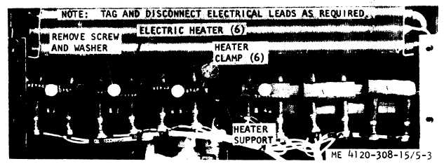
Figure 5-3. Electric heater, removal and installation.
signed to limit the minimum low side pressure to
58 (± 2) psig at the compressor inlet line to pre-
vent ice from forming on the evaporator coil
during low temperature operation. Valve is preset
to a pressure setting of 58(±2) psig.
b. Testing.
(1) Install refrigerant test pressure gages
(para 6-6).
(2) With unit operating in the normal
COOL mode, observe the suction pressure. Pres-
sure should be a minimum of 56 psig.
(3) Restrict 90 percent of inlet evaporator
airflow. If suction pressure drops below 56 psig,
remove adjusting screw cap and turn counter-
clockwise until pressure reaches 56 psig. If a
minimum pressure of 56 psig cannot be attained,
valve is defective and should be replaced.
c. Removal.
(1) Discharge the refrigerant system (par
6-3).
(2) Refer to figure 3-4 and remove the top
access cover.
(3) Refer to figure 5-5 and remove the regu-
lating valve.
d. Installation.
(1) Install the regulating valve in reverse
order of removal. Refer to paragraph 6-3 for sol-
dering procedures.
(2) Pressure test, evacuate, and recharge
the refrigerant system (para 6-5).
5-14. Compressor Bypass Solenoid Valve
a. General. The compressor bypass solenoid
valve is a normally open solenoid valve installed
in the system to stop the flow of liquid refriger-
ant to the evaporator coil when the thermostat
does not call for cooling. Refer to figure 6-1 for
normal flow patterns in both cooling and bypass
mode of operation.
b. Testing.
(1) Remove the junction box (para 3-30).
(2) Start the air conditioner (para 2-8). If
the solenoid valve fails to click upon start of op-
eration, stop the unit and check the electrical
connection and coils.
(3) Disconnect the electrical connector.
(4) Check for continuity between the coil
leads. If continuity is not indicated, coil is defec-
tive and should be replaced.
(5) Check for continuity between the air
conditioner casing and either of the coil leads. If
continuity is indicated, coil is defective and
should be replaced.
c. Removal.
(1) Discharge the refrigerant system (para
6-3).
(2) Refer to figure 5-6 and remove the com-
pressor bypass solenoid valve.
d. Installation.
(1) Install the solenoid valve in reverse
order of removal.
(2) Pressure test, evacuate and recharge the
refrigerant system (para 6-5).
5-15. Pressure Equalizer Solenoid Valve
a. General. The pressure equalizer solenoid
valve is a normally open solenoid valve installed
in the system to insure rapid pressure equaliza-
tion during the compressor off cycle. The valve is
normally open during the compressor off cycle.
5-7
|