|
| |
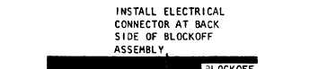
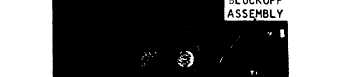
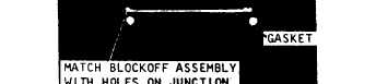
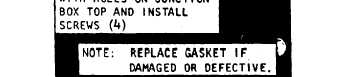
Figure 2-2 Blockoff assembly installation
(3) Refer to figure 2-3 and install the dis-
charge and intake grilles to prevent foreign ob-
jects from entering ducts.
d. Chemical and Biological Filter Installation.
When conditions require operating the air condi-
tioner using a chemical and biological filter. the
unit should be prepared for operation as follows:
(1) Refer to figure 2-3 and install the dis-
charge and return air ducts.
(2) Refer to figure 3-6 and remove the CB
intake duct cover.
(3) Refer to figure 2-3 and attach duct from
a suitable CB filter to CR intake duct.
(4) Close fresh air damper door by pulling
damper door control chain. The air conditioner is
now ready for CB mode operation.
c. InstalIing Unit. Bolt unit to floor or other
flat surface. Refer to base plan (fig. 1-3) for di-
mensions. Remove condensate drain plug (fig.
1-2), connect drain hose, if required, to drain
connections, or to one of the alternate drain con-
nections. Be sure drain connections not being
used are plugged.
f. Power Source. The air conditioner operates
on 208 volts, 50/60 Hertz, 3-phase power. The
power input receptacle is located at the rear of
the unit above the condenser coil inlet. Alternate
locations for electrical power connections are pro-
vided at both sides of the unit. Any location may
be used by interchanging the receptacle at the
rear of the unit and one of the cover plates at
each side of the unit. Be sure the unused recepta-
(cle locations are covered to prevent air from
being drawn through the opening.
g. Conversion to Remote Control. The control
panel may be removed from the air conditioner to
operate the unit by remote control. To relocate
the control panel proceed as follows :
(1) Disconnect electrical power from air
conditioner.
(2) Refer to paragraph 2-2 and install the
blockoff assembly.
(3) Refer to figure 2-1 and install the capil-
lary tube and sensing bulb on rear of control
panel.
(4) Refer to figure 2-4 and connect inter-
connecting cable to connector on blockoff assem-
bly and receptacle on control panel.
Note: Remote control connection can be made as
above or by removing the electrical connector from the
blockoff assembly and installing it in one of the alternate
electrical connection locations shown on figure 1-1 and
1-2.
2 - 3
|