|
| |
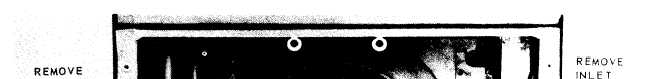
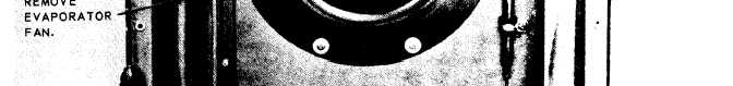
Figure 3-6. Evaporator fan and inlet ring, removal and installation.
(1) Remove the air intake grille (para 3-6).
(2) Refer to figure 3-6 and remove the inlet
ring and evaporator fan.
b. Cleaning and Inspection.
(1) Clean the fan and inlet ring and dry
thoroughly.
(2) Inspect the fan for bent fins or other
damage. Inspect the inlet ring for damage.
(3) Replace damaged components.
c. Installation. Install the evaporator fan and
inlet ring by reversing the order of removal.
3-21. Condenser Fan
a. General. The condenser fan is of the airfoil
type to reduce noise and vibration.
b. Removal.
(1) Remove the fan guard (para 3-19).
(2) Refer to figure 3-7 and remove the con-
denser fan.
Note. The condenser fan may be difficult to re-
move from the shaft if it has been inplace for an extended
period of time. If the fan will not pull off with minimum
effort, utilize a suitable puller. Place the pulling ends
carefully so as not to damage the fan blades.
c. Cleaning and Inspection.
(1) Clean the fan and dry thoroughly.
3-10
(2) Inspect the fan for damage. Check the
balance weights for looseness; tighten loose
weights. Inspect motor shaft for gouging.
(3) Replace damaged fan.
d. Installation.
(1) Clean the motor shaft and remove small
scratches or burrs with a crocus cloth.
(2) Position fan on shaft and push inward}
be careful to maintain the fan 90° to shaft. Fan
should be mounted with minimum of effort. If the
fan resists the pushing motion, apply crocus cloth
to the motor shaft again until the fan mounts pro-
perly.
(3) Replace the fan guard.
3-22. Damper Door Control
The damper door control consists of a chain and
spring assembly and will require little mainte-
nance when properly handled, Should mainte-
nance be necessary, remove the intake grille
(para 3-6) disconnect the chain from the spring,
and replace damaged component.
3-23. Electrical Wiring System
The electrical wiring system (figs. 1-3 and 1-4)
should be inspected frequently to avoid damage
or failure during operation. Any wiring showing
|