|
| |
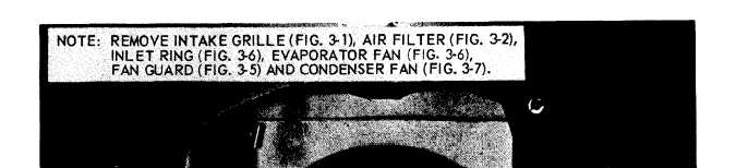
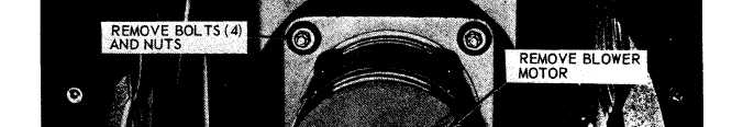
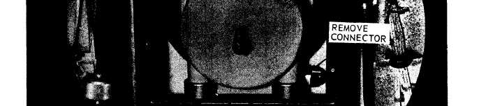
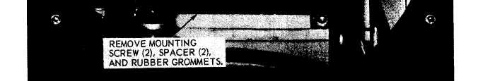
Figure 3-8. Blower motor assembly, removal and installation.
b. Removal.
(1) Remove the fan guard (para 3-19) and
condenser fan (para 3-21 ).
(2) Remove the evaporator fan and inlet
ring (para 3-19).
(3) Refer to figure 3-8 and remove the
blower motor assembly.
c. Installation. Install the blower motor assem-
bly, fans, and guards by reversing the order of
removal.
3-25. Power Connector Receptacle
The power receptacle (fig. 2-2) is mounted on the
case with four screws. When any receptacle
connector is moved to an alternate position, re-
place the connector with the cover that was re-
3-12
moved from the alternate position. When chang-
ing the location of the receptacle connector, be
certain that all leads to the receptacle are han-
dled with care and not pulled loose or damaged.
Remove the four mounting screws and ease the
leads around components so as to assure clear-
ances for future maintenance. Mount the recepta-
cle connector and cover assembly.
3-26. Control Panel
a. General. The control panel, housing the
selector switch and temperature control switch, is
mounted on the control box.
Note. Some applications may require remote locations
for this panel.
b. Removal.
|