|
| |
Table 5-1. Troubleshooting
Malfunction
1.
2.
Compressor fails to start.
Compressor starts but fails on over-
load.
3. Suction pressure too low.
4. Discharge pressure inadequate.
5. Suction pressure high.
6.
7.
8.
9.
Discharge pressure high.
Suction and discharge pressure low.
High suction pressure with low dis-
charge pressure.
System losing cooling capacity.
a.
b.
a.
b.
Compressor
thermostatic switch
(internal) open or defective.
Compressor defective.
Expansion valve defective
correctly set superheat.
Discharge pressure too high,
Compressor defective.
Defective liquid line bypass
uid line solenoid valves.
Dehydrator defective.
Compressor defective.
a. Liquid line solenoid valve
tive.
b. Hot gas bypass valve defective.
c. Compressor defective.
d. Pressure relief valve inoperative,
e. Frost on the evaporating coil.
Overcharge of refrigerant.
Lack of refrigerant
Compressor defective
System pressure inadequate
Outdoor ambient
temperature
Normal gage
pressure
(p.s.i.g.)
Suction
Discharge
Probable cause
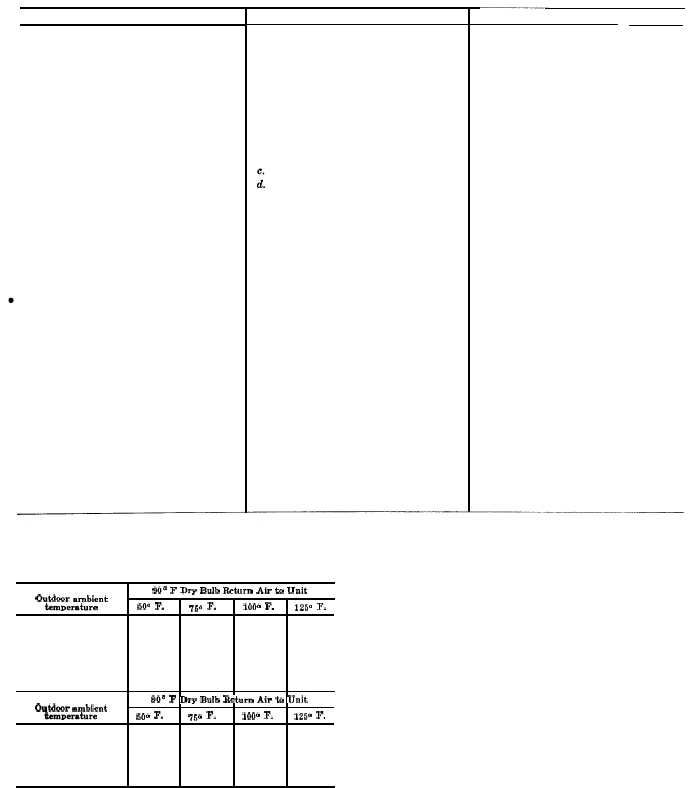
Table 5-2. Normal Operating Pressure
Outdoor ambient
temperature
Normal gage
pressure
Suction
Discharge
or in.
or liq-
de fee-
Corrective action
a. Test the switch after compressor
is cool; if switch is open, replace
the compressor (para 5-22).
b. Replace compressor (para 5-22).
a. Replace valve if correct adjust-
ment cannot be obtained (para
5-13) or if valve fails to modu-
late refrigerant flow correctly.
b. Remove small amount of refriger-
ant (para 6-1).
c. Replace compressor (para 5-22).
d. Test control coils (para 6-5),
check valves for positive open-
ing and closing. Replace coils or
valves if defective.
Replace dehydrator (para 5-17).
Replace compressor (para 5-22).
a. Replace solenoid
valve
(para
5-16).
b. Replace bypass valve (para 5-15).
c. Replace compressor (para 5-22).
d. Adjust or erplace relief valve
(para 5-18).
e. Test pressuer relief valve, adjust
or replace defective valve (para
5-18).
Remove small amount of refrigerant
(para 6-1).
Check sight glass for appearance of
bubbles, add R-22 refrigerant as
required. Check for leaks (para
6-1).
Replace compressor (para 5-22).
Refer to instructions in para 5-10.
Install pressure gages on the service valves and
90° F Dry Bulb Return Air to Unit
turn the valves two turns to open, exposing gages
50’3 F.
75° F.
1000 F.
125° F.
to the system pressures. Compare gage readings
to the normal operating pressure indicated in
table 5-2 below:
58–65
58-70
65-75
75-90
135-155
185–205
275-295
400-420
SOO F Dry Bulb Re turn Air to Unit
50° F.
75° F.
1000 F.
125° F.
58-65
58–70
60-75
65-75
130-150
180-200
270–290
390-410
5-2
|