|
| |
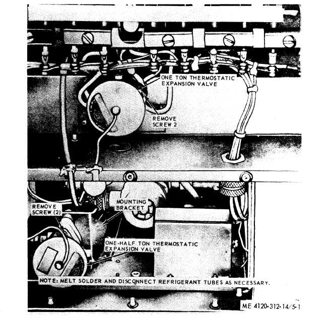
Figure 5-1. Thermostatic expansion valves, removal and installation.
fore opening the system; this delay will help to
prevent the formation of condensation on the in-
side walls of the tubing. Plug or cap all openings
as a part is removed from the system to minimize
the entry of contaminants and moisture into the
system.
(3) Use a silver solder on all soldered con-
nections. Continually pass dry nitrogen through
the tubing or connection being soldered.
5-12. Back Pressure Regulating Valve
a. General. The back pressure regulating valve
controls the refrigerant pressure in the evapora-
tor to prevent evaporator freeze up. It also by-
passes refrigerant gas from the discharge line to
the suction line during bypass operation when the
switch is on COOL. The valve is pre-set to estab-
lish a minimum pressure of 57.8 PSIG in the eva-
porator.
b. Adjustment.
(1) Remove the button plug from the cap at
top of valve.
(2) Attach a service adjusting screw to read
suction pressure. Turn screw clockwise to raise
pressure and counterclockwise to reduce pressure.
Caution: Adjustment of valve only re-
quired if all other system/components are operat-
ing satisfactorily.
5-4
|