|
| |
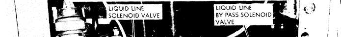
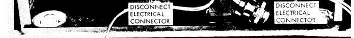
Figure 5-5. Liquid line solenoid valve and liquid line bypass solenoid valve, removal
and installation.
b. Removal.
(1) Remove the top cover (para 3-6).
(2) Discharge the system (para 6-1).
(3) Refer to figure 5-1 and remove the ther-
mostatic expansion valves.
c. Adjustment, Refer to figure 5-2 and adjust
the thermostatic expansion valves.
Caution: Never adjust the expansion valves
unless it is absolutely necessary.
Note. Both expansion valves adjust in the same man-
ner.
d. installation.
(1) Install
the thermostatic expansion
valves by reversing the order of removal.
(2) Replace the dehydrator (para 5-17).
5-14. High Pressure Cutout Switch
a. General. The high pressure cutout switch
prevents operation of the compressor when the
system pressure exceeds 445 PSIG.
b. Removal.
(1) Relieve the system pressure by dis-
charging refrigerant (para 6-1).
(2) Remove the top cover (para 3-6),
(3) Refer to figure 5-4 and remove the high
pressure cutout switch.
5-8
c. Installation.
(1) Install the high pressure cutout switch
and top cover by reversing the order of removal.
(2) Evacuate and recharge the refrigerant
system (para 6-1 ).
5-15. Hot Gas Bypass Solenoid Valve
a. General. The hot gas bypass valve is auto-
matically operated by the temperature control
thermostat. The valve controls the flow of refri-
gerant through the system when it is in the by-
pass cycle. It is closed during the cooling cycle of
operation.
b. Removal.
(1) Remove the top cover (para 3-6).
(2) Discharge the refrigerant (para 6-1).
(3) Refer to figure 5-4 and remove the hot
gas bypass valve.
c. Installation.
(1) Install the hot gas bypass valve by rev-
ersing the order of removal.
(2) Replace the top cover (para 3-6).
(3) Replace the dehydrator (para 5-17).
(4) Evacuate and recharge the refrigerant
system (para 6-1 ),
|