|
| |
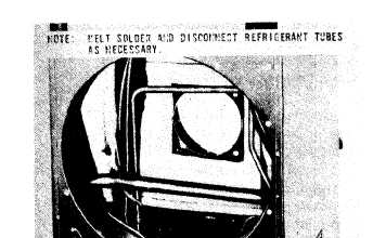
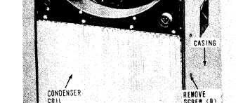
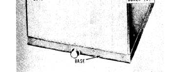
Figure 5-9. Condenser coil, removal and installation.
5-16. Liquid line Bypass Solenoid Valve
and liquid line Solenoid Valve
a. Removal.
(1) Discharge the refrigerant system (para
6-1).
(2) Remove the front access panel (para
3-3).
(3) Refer to figure 5-5 and remove the sole-
noid valves.
b. Installation.
(1) Install the solenoid valves by reversing
the order of removal.
(2) Replace the dehydrator (para 5-17).
(3) Replace the front access panel (para
3-6).
(4) Evacuate and recharge the refrigerant
system (para 6-1).
5-17. Dehydrator
a. General. The dehydrator prevents the accu-
mulation of moisture and contaminants within
the refrigerant system. The dehydrator must be
replaced each time the refrigerant system is ex-
posed to the atmosphere during the replacement
of a system component or whenever the sight
glass indicates moisture is present in the system.
b. Removal.
(1) Remove the front access panel (para
3-6).
(2) Discharge the refrigerant system (para
6-1 ).
(3) Refer to figure 5-6 and remove the de-
hydrator.
c. Installation.
(1) Install the dehydrator and access panel
by reversing the order of removal. insure proper
flow direction when installing the dehydrator.
The outlet toward the down stream side of the re-
frigerant flow.
(2) Evacuate and recharge the refrigerant
system (para 6-1).
5-18. Pressure Relief Valve
a. General. The pressure relief valve, located
immediately beneath the dehydrator, prevents ex-
cessive pressure in the refrigerant system.
b. Removal.
(1) Remove the f rent access panel (para
3-6).
(2) Discharge the refrigerant system (para
6-1).
(3) Refer to figure 5-6 and remove the pres-
sure relief valve.
c. Installation.
(1) Install the pressure relief valve by rev-
ersing the order of removal.
(2) Replace the dehydrator (para 5-17).
(3) Replace the f rent access panel (para
3-6) .
(4) Evacuate and recharge the refrigerant
system (para 6-1).
5-19. Sight Glass
a. General. The sight glass indicates when
more refrigerant may be required and if moisture
is present in the refrigerant circuit.
b. Removal.
(1) Discharge the refrigerant (para 6-1).
(2) Remove top cover (para 3-6).
(3) Sweat the sight glass connections loose.
Protect the surrounding area from heat or flame.
(4) Refer to figure 5-7 and remove the sight
glass.
c. Installation.
(1) Install the sight glass by reversing the
order of removal.
(2) Solder sight glass connections. Protect
the surrounding area from heat.
5-12
|