|
| |
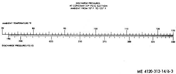
Figure 6-3. Pressure-temperture chart.
Start unit and weigh in 3.5 pounds of refrigerant
R–22. Continue adding refrigerant until sight
glass indicates full.
Note. Operate unit at COOL position during
charging operation. Partially block discharge grill with
cardboard baffle. Adjust baffle until suction pressure gage
reads 55 psig pressure. Continue adding refrigerant
slowly, while maintaining 55 PSIG suction pressure by ad-
justing the baffle, until the discharge pressure gage read-
ing corresponding to the ambient temperature is obtained.
Refer to figure 6-3.
(8) Remove condenser fan and close service
valves; close refrigerant drum shutoff valve and
stop the unit.
(9) Disconnect the pressure manifold from
the service valves. Replace valve caps.
(10) Inspect the compartment
and install the condenser fan and
(para 3-21).
6-3. Blower
Section II. BLOWER
Motor Assembly
thoroughly
fan guard
6-2. Refrigerant Tubing
The refrigerant tubing used in the air conditioner
consists of copper tubing and the necessary fit-
tings. The joints of the refrigerant tubes are sol-
dered with silver solder (para 5-11 f (3) ). Inspect
the tubing and fittings for leaks, cracks, breaks,
or signs of excessive wear. Replace any defective
tubing or fittings with material of the same size,
type, and shape. When applying heat to the tub-
ing close to a solenoid valve, direct the heat away
from the valve body. Keep flame away from dis-
tributor of expansion valves. Test all tubing re-
pair for leaks.
Note. If the refrigerant system has been exposed to the
atmosphere by the removal of any tubing or a fitting, re-
place the dehydrator and pressure test and evacuate the
system before recharging. When removing or replacing
tubing, pass dry nitrogen through the lines to prevent cop-
per oxides.
MOTOR ASSEMBLY AND SOLENOID VALVES
a. On-Equipment Testing. Prior to removing
the blower motor assembly, test for open wind-
ings or shorts as follows:
(1) Disconnect the receptacle connector
from the control box. Test for continuity across
each combination of two motor terminals. Lack of
continuity indicates an open winding.
(2) Place one contact of tester against
motor housing and the other on one of the termi-
nals, continuity will indicate a grounded motor.
(3) Test the motor stator for insulation res-
istance as instructed in TM 5-764. The insulation
resistance should measure not less than 0.5 me-
gohms.
Note. The resistance measurement should be used
only as a guide, taking into consideration the accuracy of
the instrument used, test lead resistance, and ambient
temperature at time of test. If more precise measurement
is required, an instrument such as a Kevin or Wheatstone
bridge should be used, or comparative measurements be-
tween the suspected component and a like item known to
be in good condition.
In all cases where a megometer is used for test-
ing, make certain that the unit is thoroughly dry.
Wet condemnation tolerances should be consid-
ered.
(4) Connect the motor leads to a proper
source of power. Use a hook type ammeter and
read the amperage flowing in each of the motor
leads. On model CH-420-1 the ammeter should
6-4
|