 |
|||
|
|
|||
|
Page Title:
Table 4-3. Normal Operating Pressures and Currents. |
|
||
| ||||||||||
|
|
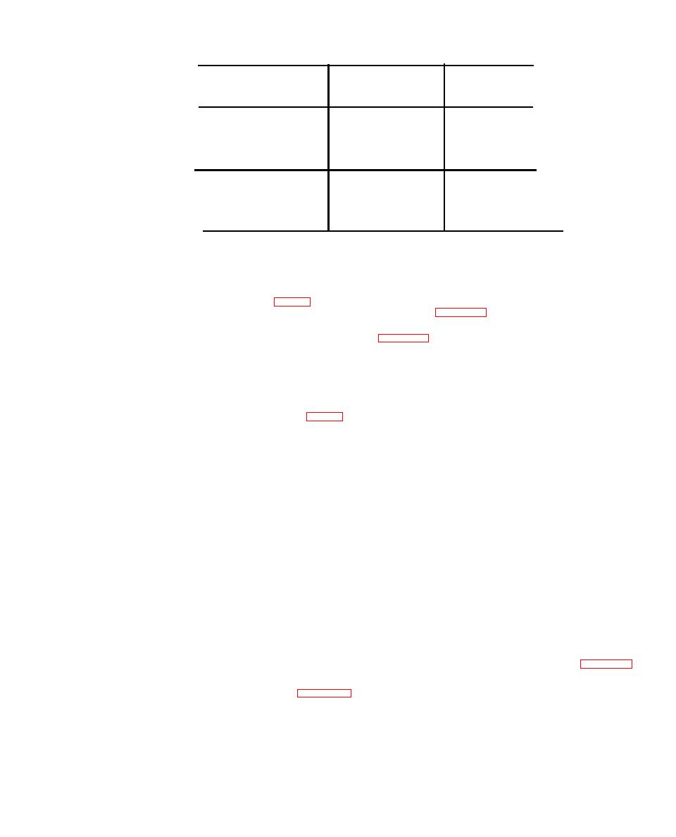 Outdoor Ambient
95 F
0
120 F
FDb
Temperature-
(35 C)
( 4 8 . 9 C)
90FDb
R e t u r n Air to
(26.7 F)
( 3 2 . 2 C)
75 F Wb
67 F Wb
Unit-
FDb
and
Wb
(19 C)
(24 C)
Gage Pressure
60-70
75-90
Suction-PSIG
260-270
360-380
Discharge-PSIG
14-16
18-20
Current-Amperes
Note: Db (Dry bulb)
Wb (Wet bulb)
required for the suction strainer. The only in-
spection being, checking for refrigerant leaks
T w o solenoid valves are used in the air conditioner.
particularly at the inlet and outlet suction line
B o t h are normally open valves. L1 (fig. 1-6) is the
c o n n e c t i o n s (para 4-55). A clogged suction strainer
liquid line solenoid valve. It is controlled by the
would result in excessively low suction pressure
thermostat setting. W h e n e v e r t h e i n t a k e a i r
temperature reaches the setting of the thermostat
e v i d e n c e d by frost forming on the exterior surfaces.
t h e electrical circuit to the L1 solenoid is energized
thus closing the valve to stop the flow of refrigerant
Thermostatic
Expansion
Valves
through the evaporator coil. When the temperature
a. General. Two thermostatic expansion valves
rises, the valve is de-energized and thus opens
a r e used in the air conditioner. One expansion valve
p e r m i t t i n g liquid refrigerant flow to the evaporator
controls the rate of flow of liquid refrigerant into
t o resume cooling. The L2 solenoid valve (fig. 1-6)
the evaporator coil during the cooling cycle of
i s the compressor by-pass solenoid and is piped in
operation. The second expansion valve functions
parallel with the compressor. When the compressor
w h e n the unit is in the by-pass cycle of operation.
stops the valve de-energizes and assumes its nor-
E a c h valve is equipped with a super heat setting or
mally open position thus allowing pressure to
0
adjustment, 10 F. for the main valve and 25 F.
equalize from the discharge to the suction side of
for the by-pass valve to assume efficiency in the
the compressor. To determine if L1 is functioning
refrigerant system. The adjustment procedures may
properly, observe the sight glass and if flow is
be applied to either or both expansion valves.
noted, valve is open. Adjust thermostat to the
Adjust only when absolutely necessary and then
higher setting and flow should stop. Check L2 by
only during the cooling cycle.
r e m o v i n g the top panel of the unit and feeling the
b. Adjustment.
l i n e out of the valve. If line is warm, valve is not
(1) Tape the bulb of a thermometer to the
closing when energized. Check coil of both valves
suction tube near the sensing element. Insulate the
f o r continuity and ground by using an ohmmeter. It
thermometer bulb.
s h o u l d r e a d a r e s i s t a n c e o f SO o h m s , a p -
(2) Install a suitable pressure gage at suction
proximately.
service valve.
(3) Operate the unit for approximately 30
minutes or until thermometer reading stabilizes.
T h e air conditioner is equipped with a suction and
(4) Check thermometer and pressure gage
a discharge service valve located behind an access
readings. Compare readings with figure 4-2.
p a n e l next to the CBR duct cover at the rear of the
Thermometer reading should be approximately
air conditioner. Test of the service valves consists of
1 0 F. for the valve feeding the evaporator coil and
c h e c k i n g to insure that they do not leak. (para. 4-
25 F. for the by-pass valve, higher than the
5 5 ) . Be sure that the caps are securely fastened to
saturated refrigerant temperature.
the service valve-openings.
(5) Remove cap from side of valve. If tem-
4-61 Suction Strainer
perature reading is high, turn adjusting screw
The suction strainer is an integral part of the
counter-clockwise approximately one turn for each
c o m p r e s s o r . It serves to prevent large contaminants
4 F. that temperature is high. If temperature
(particles measuring greater than 5 microns) from
reading is low turn adjusting screw clockwise
entering the compressor. Service is normally not
approximately one turn for each 4 F. that
|
|
Privacy Statement - Press Release - Copyright Information. - Contact Us |
