 |
|||
|
|
|||
|
Page Title:
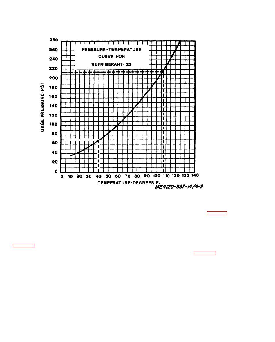
Figure 4-2. Refrigerant 22 pressure-temperature chart. |
|
||
| ||||||||||
|
|
 temperature is low, Install cap on side of valve
when adjustment is completed. Remove gage and
thermometer,
4-63. Pressure Relief Valve
refrigerant system. When the sight glass indicates
t h a t moisture is present in the system (para 4-57), it
T h e pressure relief valve is a safety device used to
should be reported to DS Maintenance for
relieve refrigerant pressure if it attempts to go
correction.
higher than the system is designed to withstand.
Proper relief pressure is 540 PSIG. The only in-
4-66. Evaporator Coil
s p e c t i o n required for this device is to insure that the
a. Inspection and Test. Inspection and test of
v a l v e or its connection to the tubing is not leaking
t h e evaporator coil consists of examination for bent
fins and accumulation of external contamination
4-64. Fluid Pressure Regulator
and test for refrigerant leaks (para 4-55).
b . Service. Scrub the external portion of the coil
The pressure regulator valve is incorporated in the
with a stiff bristle brush or soft bristle wire brush to
refrigerant system to regulate pressure on the
remove scale and corrosion. Take care not to
suction side of the system and maintain it a
damage the fins. Use compressed air to blow out
minimum of 30 PSIG at all times the air con-
l o o s e material. Wipe the coil with a cloth dampened
d i t i o n e r is operating on the cooling cycle. To check
w i t h dry cleaning solvent per Federal Specification
t h e valve, install a gage on the suction service valve
P-S-661. Bent fins may be straightened with a fin
a n d increase the control thermostat setting until the
c o m b (12 fins per inch spacing) or with needle nose
l i q u i d line solenoid valve closes. This will lower the
pliers.
suction pressure. The fluid pressure regulator is
factory set and sealed at 58 PSIG.
4-67. Condenser Coil
4-65. Dehydrator
a. Inspection and Test. Inspection and test of
t h e condenser coil consists of examination for bent
T h e dehydrator is a filter and moisture drier for the
|
|
Privacy Statement - Press Release - Copyright Information. - Contact Us |
