 |
|||
|
|
|||
|
Page Title:
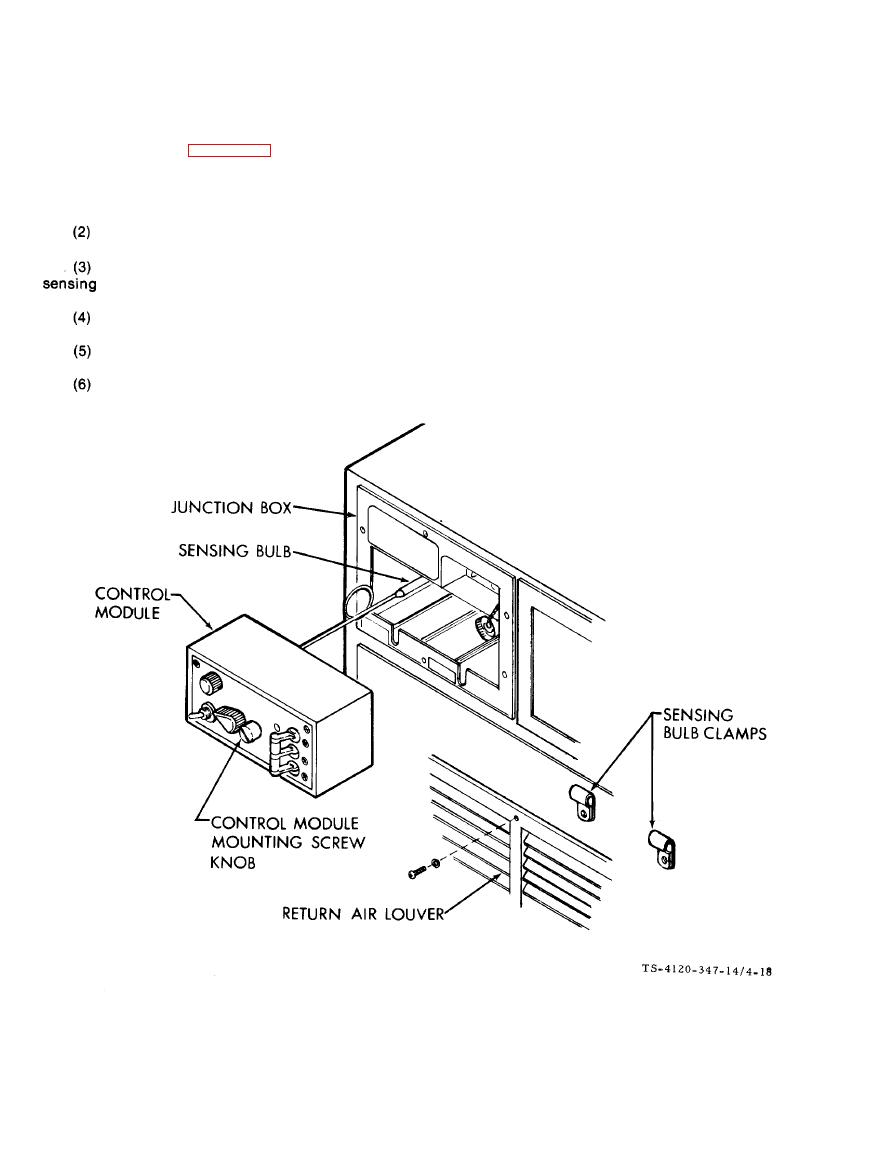
Figure 4-18. Control Module Removal |
|
||
| ||||||||||
|
|
 TM5-4120-347-14
(2) Repairs are limited to replacement of individual components and repair of wire connections.
c. Installation (See figure 4-18.)
(1) Carefully work the sensing bulb through the junction box frame and into the two mounting clamps
behind the return air louver,
Tighten clamp screws.
Slip the control module into the opening in the junction box, Take care not to crush or kink the
bulb capillary line.
Tighten the control module mounting screw.
Install the return air louver.
Connect power at power source.
4-44
|
|
Privacy Statement - Press Release - Copyright Information. - Contact Us |
