 |
|||
|
|
|||
|
|
|||
| ||||||||||
|
|
 TM5-4120-347-14
(d) See wiring diagram figure 4-5 and install the resistor R1 on the transformer. Secure the resistor to
the transformer with a tie down strap.
(e)
Attach the transformer to the unit with four screws and lock washers.
(f)
Slip heat shrinkable insulation tubing on the ends of all wires that are to be soldered.
See wiring diagram figure 4-5 and tags and connect all wire leads. Remove the tags.
(g)
(h)
Slip heat shrink tubing over all exposed solder connections and shrink in place.
(2) Rectifier/Capacitors.
(a) Tag and disconnect wire leads,
(b) Remove two screws and pull rectifier from unit.
(c) Remove capacitors.
(d) Install capacitors.
(e) Attach the rectifier to the unit with two screws.
(f) See wiring diagram figure 4-5 and tags and connect all wire leads. Remove the tags.
(3) Install the junction box and control module. (See paragraphs 4-27 and 4-33.)
(4) Install the top front cover.
(5) Connect power at the power source.
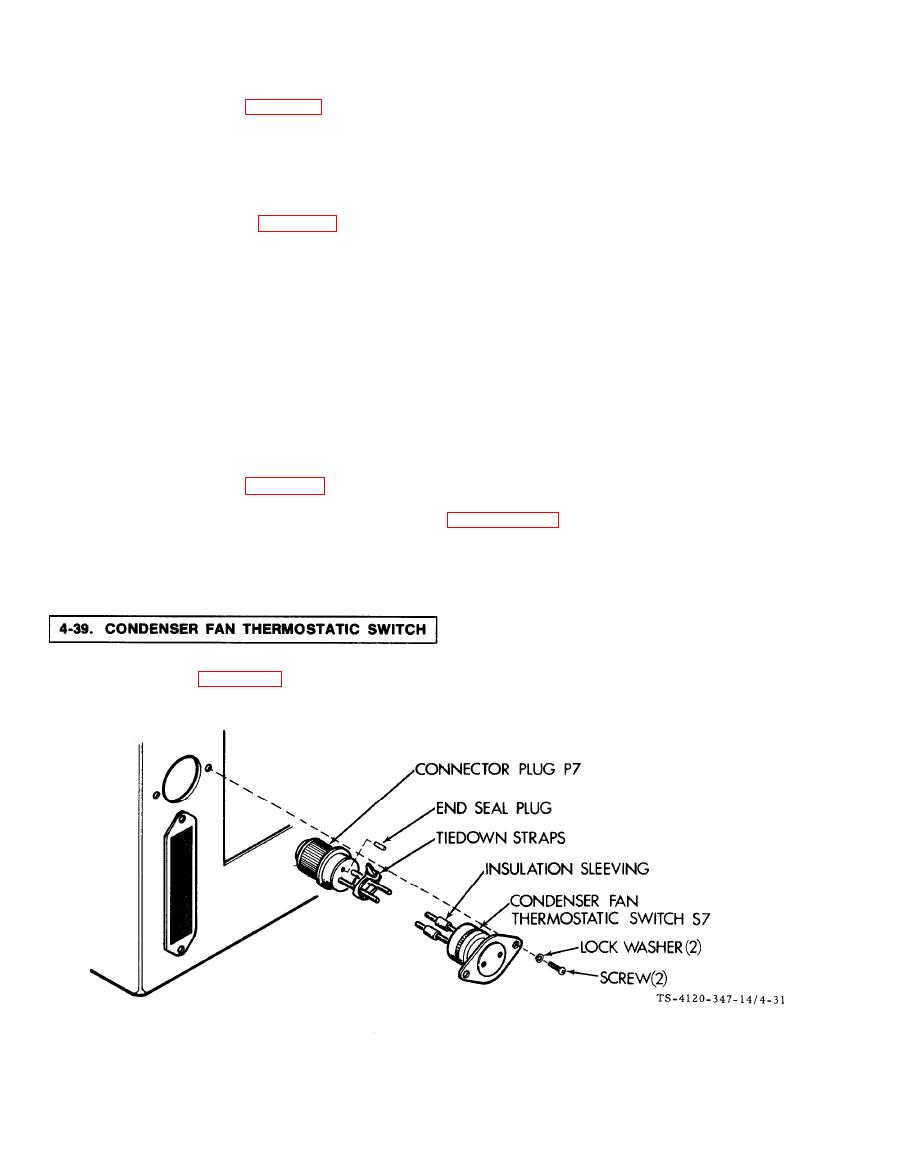
The condenser fan thermostatic switch is located on the lower left rear corner of the unit above the fresh air
ventilation guard. See figure 4-31.
4-64
|
|
Privacy Statement - Press Release - Copyright Information. - Contact Us |
